Calculating and Reporting Distributed Wall Reactions for Pinned FE Surface Edges
When designing concrete structures within the MasterSeries suite, particularly when utilising the Finite Element (FE) Analysis module, it is often necessary to ascertain the distributed reactions from structural walls that are modelled as FE surfaces. This guidance will walk you through setting up your model and using the Section Line Diagram feature to effectively visualise and report these reactions.
1. FE Surface Setup for Walls
Defining Edge Supports
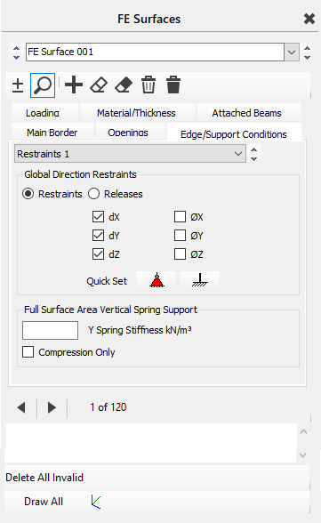
Access the Edge/Support Conditions tab for your wall FE surface. You can utilise the Quick Set > Pinned option to apply a pinned line support along the base of your wall. This restraint prevents translational movements in the dX, dY, and dZ directions. Remember to allocate these support edges by selecting the bottom of the shear wall as the support location.
2. Analysis
Once your FE wall surface is correctly defined with its geometry, material properties, and pinned edge supports, proceed with the structural analysis. MasterSeries employs matrix methods to solve the equations of the stiffness matrix.
- Go to Analysis > Static Analysis.
- Choose the appropriate analysis type, typically Space Frame for 3D models or Plane Frame for 2D structures. The software will automatically save your file and conduct the analysis.
3. Extracting Distributed Wall Reactions Using Section Diagrams
To visualise and report the distributed wall reactions, you will leverage the Section Line Diagram functionality within the graphical analysis results for shell elements. This is particularly useful for reviewing axial or shear force distributions across shear walls, which represent the reactions at your pinned base.
- Access Graphical Analysis Results: After the analysis is complete, navigate to Results > Graphical Analysis Results.
- Switch to Shell Elements: Select the Shell Elements tab at the top of the graphical analysis output dashboard. This view displays results as contour maps for your FE surfaces.
- Create a Section Line Diagram: Within the Shell Elements tab, locate the Section Diagrams options. Choose to add a Line Diagram.
- Define the Section Line: Draw a section line along the base of your wall, precisely where the pinned edge support is defined. This line will represent the path along which you want to extract the distributed reaction.
Select Reaction Type: For a pinned support at the base of a wall, the reactions will primarily be the axial forces along the wall's length, depending on the load direction.
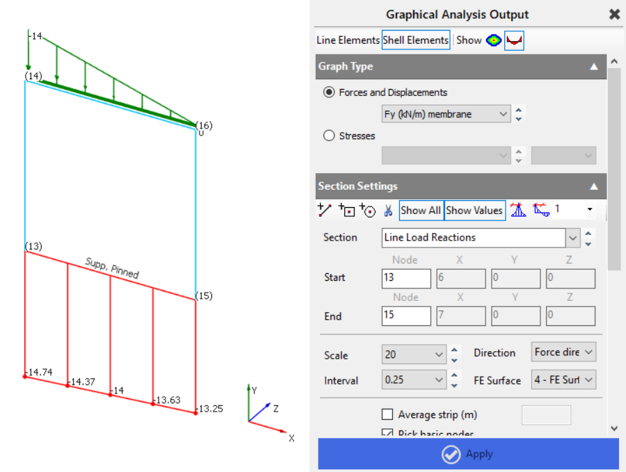
- Under the section diagram settings, you can select to plot Axial forces for the associated force direction (e.g., Fy (kN/m) membrane)
- Note: While "Spring Support Reactions" are an option for FE surfaces with spring stiffness , for explicitly pinned edge supports, the shear/axial forces at the boundary are the most direct representation of the reaction transfer.
- Review and Scale: Review the generated diagram to observe the distribution of forces along the wall's base. You can adjust the scaling to enhance clarity.
4. Total Forces at the Base of a Wall
To calculate the total forces at the base of a wall, we need to ensure the software captures the full wall width when extracting results. This is done by creating a section line through the wall and instructing it to average the results across the entire wall length.
Creating the Section Line
Add a new section line from the mid-point at the base of the wall to the mid-point at the top.
The Node Start box will highlight in blue — select a node at the bottom of the wall to auto-fill its X, Y, and Z coordinates.
Next, select a point at the top of the wall in the same vertical plane to define the line.
Depending on your wall orientation, manually enter the mid-point offset in the remaining direction (X or Z) to position the line at the wall’s centre.
Tick the Average Strip box and enter the total wall length (m) — this ensures forces are averaged over the full wall width.
Axial Forces
In the results selector, choose Fy (membrane) – this represents the in-plane axial force in the local Y-axis (kN/m).
Click Apply to view results.
Multiply the averaged Fy value by the total wall length to obtain the total axial force across the wall base (kN).

Axial Force Results

Shear Forces
For shear, select Fxy (membrane) – this gives the in-plane shear force in the local XY-plane (kN/m).
Again, multiply the averaged Fxy value by the total wall length to determine the total shear force across the wall base (kN).

By defining a vertical section line at the wall mid-point, averaging across the total wall width, and multiplying the averaged membrane results by that width, you can accurately determine the total axial and shear forces acting at the base of the wall.