Changing the local axis for a single Finite Element (FE) surface panel within MasterSeries
Each FE surface panel in MasterSeries possesses its own local coordinate system, defined by an x-y plane, with the z-direction perpendicular to the surface. The positive z-axis denotes the "top" of the FE surface. This local system is crucial for interpreting FE results.
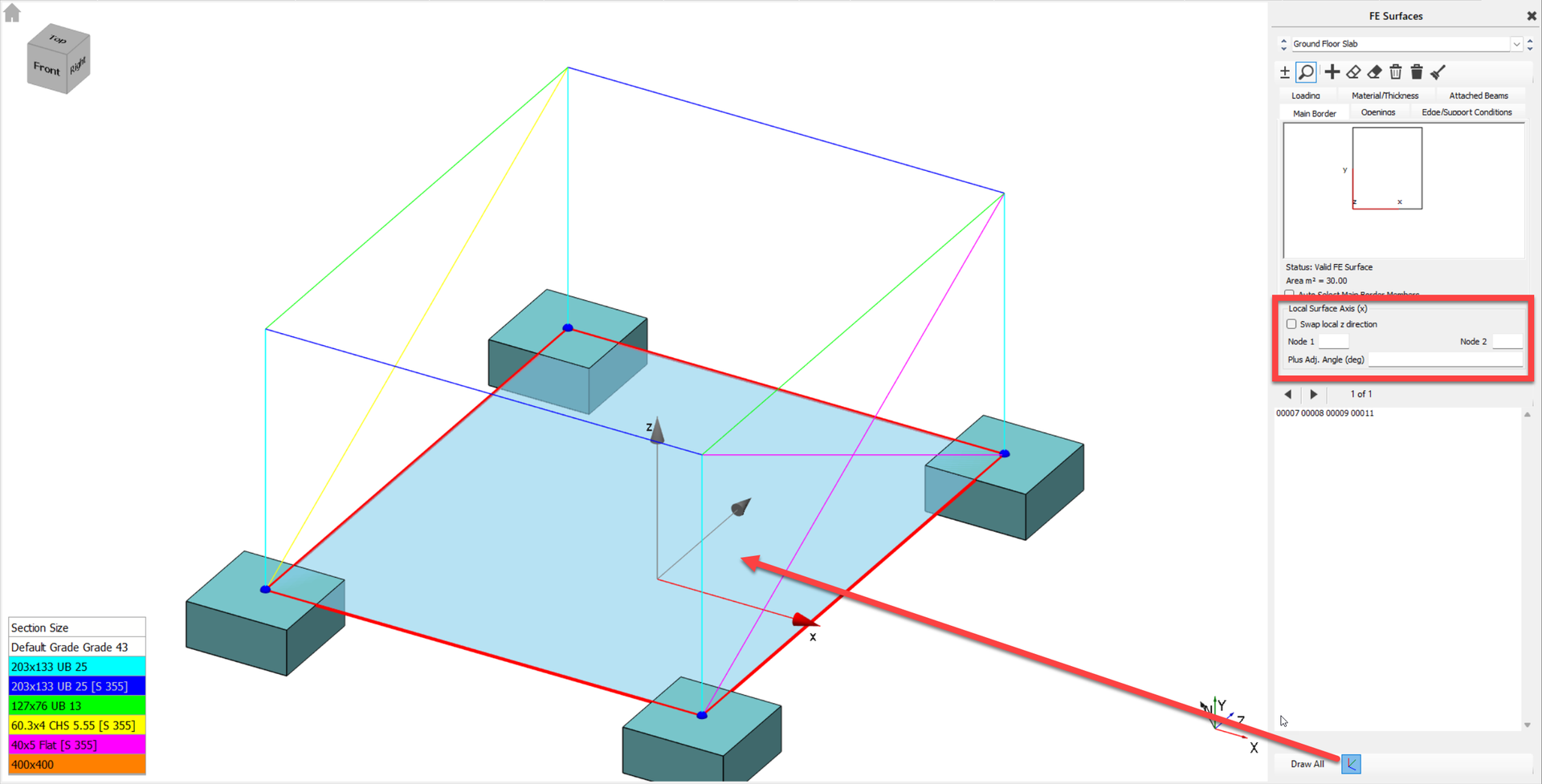
To modify the local axis of a specific FE surface panel, you have several options:
- Swapping the Local Z-Direction: You can reverse the direction of the z-axis for an FE surface. This action automatically reorients the y-axis as well, ensuring compliance with the Right-hand rule for coordinate systems.
- Controlling X-Axis Alignment: The orientation of the local x-axis can be precisely controlled by aligning it with two selected boundary nodes. You define the direction "from" Node 1 "to" Node 2, and these nodes do not necessarily need to be adjacent. The key plan in the right-hand pane will visually reflect this change.
- Applying a User-Defined Rotation: For even finer control, you can specify a rotation angle in degrees relative to the line defined by your chosen Node 1 and Node 2. This functionality is accessible through the "User Coordinate System" option, typically found within the "Result Axis" area when reviewing shell elements results. For example, you might set an angle to -30 degrees to adjust reinforcement orientation.
The software provides graphical indicators to show the local axis direction for a selected surface. When making these adjustments, it's worth noting that changes to the local mesh intensity for column heads or other specific areas can be set, which will refine the mesh within a defined radius around selected nodes.