Modelling the Real World Effects of Roof Cladding on a Portal Frame
Overview
In a real portal frame building, the primary steel frame does not act completely alone. The roof sheeting, purlins, side rails, bracing, fixings, and cladding rails can provide restraint and some in-plane stiffness to the structure. This is often referred to as diaphragm or stressed-skin behaviour.
However, this behaviour is highly dependent on the actual cladding system, fixing details, purlin arrangement, openings, rooflights, edge members, and installation quality. For this reason, the stiffness of the roof system should not usually be assumed as a simple rigid diaphragm unless it has been specifically justified.
In MasterSeries, users may attempt to represent some of these effects by adding longitudinal roof ties, transfer members, or stiff deck elements. These modelling choices can significantly affect the analysis results and should be treated as engineering assumptions.
Roof ties and transfer members
When roof tie or transfer members are introduced into a model, they create a longitudinal load path between the portal frames and the braced bays. This can help represent the way secondary roof steelwork and cladding may distribute forces in the real structure.
- In MasterPort, this can be generated through the Bracing tab by setting T = Y for the roof bracing line. This inserts transfer members so the roof bracing system has a continuous load path back to the braced bay.
- In MasterFrame, the same behaviour can occur where longitudinal roof ties or equivalent members are modelled manually along the roof length.

Why axial forces can appear in roof ties under gravity load cases
Users may notice significant axial forces in roof ties or bracing members even in dead and live load cases. This can occur because the longitudinal members are part of the analytical model and therefore contribute to the stiffness of the structure.
As portal frames deflect under gravity loading, adjacent frames may not move by exactly the same amount. If longitudinal tie members connect those frames together, the analysis enforces compatibility between the connected nodes. This can generate push/pull axial forces in the ties.
- The size of these axial forces depends on several factors, including:
- The stiffness and section size of the longitudinal tie members.
- The stiffness of the portal frames themselves.
- The amount of frame deflection.
- The bay spacing and length of the building.
- The connectivity between the ties, rafters, bracing, and support members.
- The restraint and release conditions assigned to the members.
For example, the introduction of the transfer elements can effect the behaviour and cause a longitudinal 'thrust' to the building at eaves level, causing high axial forces within the eaves ties aka 'ring stresses', due to the stiffness of the roof in that direction with the transfer ties.
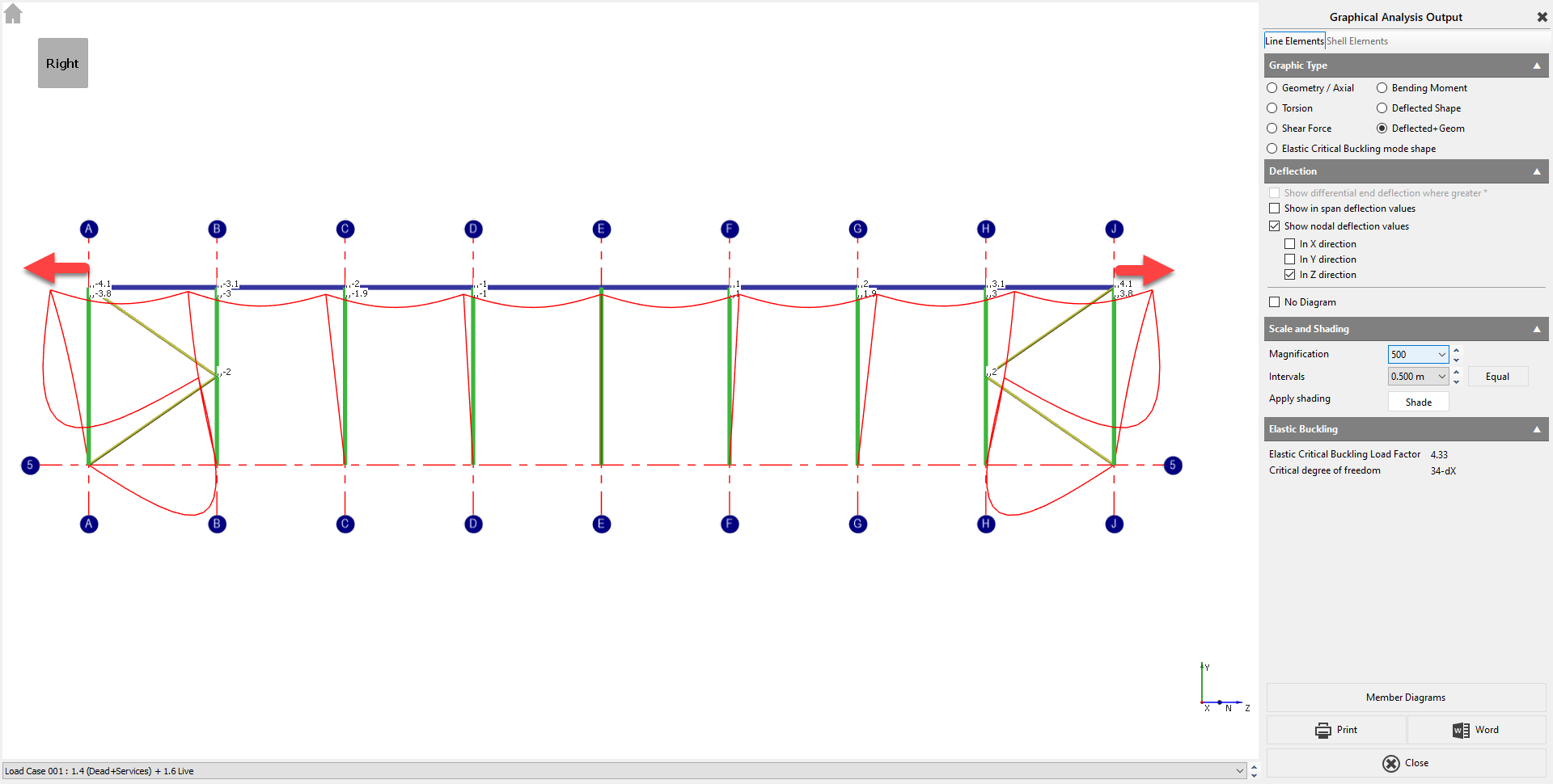
In situations like this, some users create upper and lower bound models (with and without transfer elements) to assess sensitivity, or alternatively, make design assumptions or consult the cladding manufacturer.
Modelling assumption versus real behaviour
The presence of axial force in the model does not automatically mean that the real purlin or roof bracing system will carry the same force.
In practice, many purlin systems include slotted holes, flexible cleats, laps, local slip, or connection details that do not behave as a fully continuous axial tie along the building. Roof sheeting and purlins can provide restraint and stiffness, but they are not necessarily equivalent to a fully rigid continuous steel member.
Therefore, if a continuous steel tie is modelled along the roof length, the model may attract forces that are a consequence of the assumed analytical stiffness rather than a direct gravity load path.
Upper and lower bound models
Where the stiffness contribution of the roof system is uncertain, it can be useful to consider alternative modelling assumptions. For example:
- A lower-bound model may omit roof transfer stiffness where it is not intended to participate in the primary gravity or stability load path.
- An upper-bound model may include roof ties or transfer members to assess the effect of additional diaphragm-like stiffness.
A sensitivity model may reduce or vary the section size/stiffness of the transfer members to understand how much the result depends on that assumption.
This approach can help identify whether the main frame behaviour is sensitive to the roof diaphragm or transfer tie assumptions.
Stiff Decks (MasterFrame Pro)
In MasterFrame you have the ability to model a stiff deck - however, this approach also has limitations. The SCI acknowledges that roof cladding can significantly stiffen a frame, but generally advises against relying on it for the primary stability of standard portal frames.
- Significant Stiffening: SCI P399 and SCI P397 state that portal frames clad in steel sheeting can deflect significantly less than the bare frame (reductions of horizontal deflection by over 50% are typical) due to the sheeting acting as a stressed skin diaphragm.
- Design Recommendation: Despite this, the SCI recommends that the absolute deflection limits should be compared with the calculated deflection of the bare steel frame (taking account of base fixity).
- Reasons for Caution (SCI P346): Stressed skin action is "rarely adopted in practice" for several reasons:
- Timing: The structural frame is often designed before the specific cladding system is selected.
- Fixings: Stressed skin action requires specific fixing details which must be adhered to on site. Many systems which rely on clips/friction, cannot be used for stressed skin action.
- Disruption: Rooflights and openings severely disrupt the diaphragm action.
- Risk: If you rely on the cladding to stabilise the frame (i.e., to stop it falling down or deflecting excessively), you must ensure the cladding is specified as a structural element. Future removal of the cladding (e.g., for replacement) could render the building unstable.