Concrete Beam Moment Capacity & Shear Capacity
Date: 20/09/2004
Versions: 2004.09
Program: MasterKey Concrete Beams
Moment Capacity
The MasterSeries Concrete design calculates the Moment Capacity for the provided reinforcement and not a perfectly balanced section as per 3.4.4.4. Clause 3.4.4.4 will be used for the sizing of reinforcement during auto sizing and then the Moment Capacity calculated for the provided reinforcement.
Fundamental to this process is whether compression reinforcement should be considered. In the basic data & defaults table, in the “Design & Grades” tab, you can set when you want to consider compression reinforcement by adjusting the k’ limit. If K (=M/bd2 fcu) is above this limit then compression reinforcement will be considered. Using compression steel will mean that your link longitudinal spacing is limited to 12 x (Smallest Compression Steel Diameter).
K’ limit = 0.000 = always try to use compression steel
K’ limit = 0.156 = Only use compression steel once you reach the singly reinforced limit
K’ limit = 9.999 = Never use compression steel Compression steel may not actually be used. The program will only use compression steel if it has compressive strain eg:
- If X is less than d’ then there is no compression reinforcement.
- If X is close to d’ then there is compression reinforcement but because the strain is small then the stress and thus its effect is small.
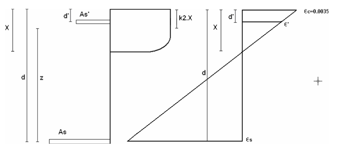
Reference: Kong & Evans: Reinforced and Prestressed Concrete, 3rd Edition. Fig 4.4-3
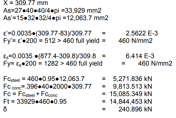
The Moment Capacity of the section is determined by positioning the neutral axis so that Fc = Ft Allowing for any code restrictions.
Note Fy and Fy' are dependant of the degree of strain in relation to the concrete 0.0035 strain.
Limiting X/D to 0.5 implys Fy always reaches yield at 460 N/mm2
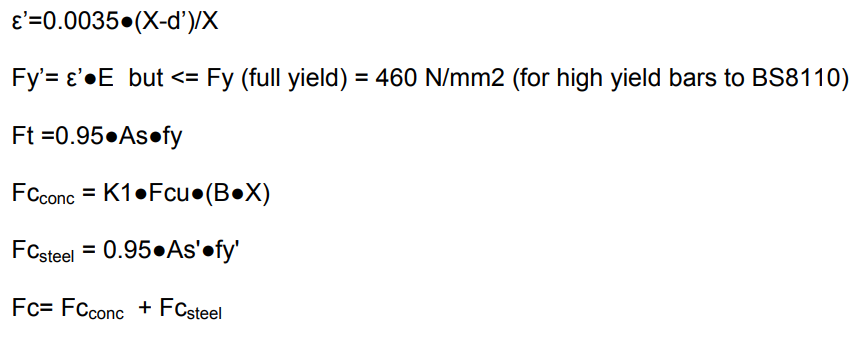
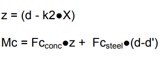
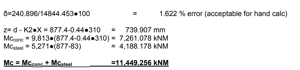
This gives us a value of X (limited by the code), Thus taking moments about "As" gives
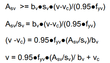
Shear Capacity
Detailed Example: Left Support Steel Hogging
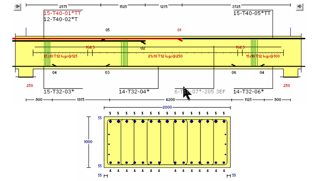
Cover = 55 mm
Fcu = 40 N/mm2
Fy = 460 N/mm2
Note in the following calculations the conversion to known units are carried out internally (eg N to kN).
K1= 0.45(1-J Fcu/52.5) = 0.396
K2= [(2- J Fcu/17.5)2 + 2] / [4D(3-J Fcu/17.5) ] = 0.444
d’= 55 + 12 + 32/2 =83 mm
d= 1000 – 55 -12 – (15D20 + 12D100)/27 = 877.444 mm
Assume X from computer iterations
Moment Capacity for Flanged beam with neutral axis in the web
When the neutral axis falls below the flange then we revert back to the Simplified rectangular stress block in BS8110.
Reference: Kong & Evans: Reinforced and Prestressed Concrete, 3rd Edition. Fig 4.4-5 (where K1 = 0.45 and k2 = 0.9/2 = 0.405)
Example Mapp = 19324.6 kNm
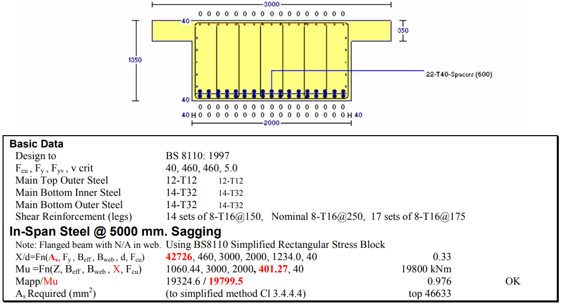
Hand Calculation for X = 401.27 mm as suggested by program.
X correct if Fc=Ft. Lets test for this value of X.
X>350 mm >>>> web in compression
As = 2 x 17 No 40 dia = 2 * 17 * pi * 20 * 20 = 42,726 mm2
d = H – cvr – lnk – bars/2 = 1350 – 40 – 16 -40-20 = 1,234 mm
Ft = 0.95 * Fy * As = 0.95 * 460 * 42726 * 1E-3 = 18,671 kN
Limit flange depth utilised to 0.9 to be slightly conservative. If we don’t the 0.9 X limit will only reduce the area of the web and would be wrong.
Hf = 0.9 * FlgDepth = 0.9 * 350 = 315.00 mm
Hw= 0.9 * X - Hf = 0.9 *401.27 – 315 = 46.14 mm
Fcf = .45 * Fcu * Bf * Hf = 0.45 * 40 * 3000 * 315 = 17,010 kN
Fcw = .45 * Fcu * Bw * Hw = 0.45 * 40 * 2000 * 46.14 = 1,661 kN
Assumed X correct if Ft = Fcf + Fcw
Fc = Fcf + Fcw = 17,010 + 1,661 = 18671 kN = Ft .
% error= 100* (Fc-Ft)/Ft = 100 *(18671-18,671)/18,671 = 0.00% error < 1% X is correct.
Moment Capacity
Mc = Mcf + Mcw
Mcf = Fcf * (d-hf/2) = 17,010 * (1234 – 315/2) = 18,311 kNm
Mcw = Fcw * (d-hf-hw/2) = 1,661 * (1234 – 315 – 46.1/2) = 1,488 kNm
Mc = Mcf + Mcw = 19,799 kNm QED