MasterFrame Finite Elements – Limits of Applicability on FE Models in terms of Span/Depth for Thick Structural Elements
Date: 14/10/2025
Versions: All
Program: MasterFrame Finite Element Analysis
Limits of applicability on FE models in terms of span/thickness for thick structural elements
MasterSeries FE utilises a 2D FE surface to model planar structures such as walls and slabs. To provide the greatest degree of flexibility in modelling such structures, the MasterFrame FE module utilises finite elements based on Mindlin-Reissner plate theory. This means that the finite elements use thick plate theory as opposed to a thin plate formulation. This allows for the modelling of structures where the thickness of the element greater than could be accommodated with a thin plate formulation.
However, despite the use of thick plate theory, care is still needed when the thickness of the element is significant relative to bending span to ensure that the FE model remains valid and that the model is a suitably accurate representation of the structure.
In structural engineering terms we are familiar with concepts such as B-regions (Bernoulli beam bending regions, where the state of bending and shear stress is assumed to follow standard section bending principals) and D-regions (discontinuous regions where standard beam bending theory does not apply due to the more complex 2D/3D stress distributions). This similar D-region concept extends to the use of plate bending elements in short thick spans where 3D effects dominate and standard bending stress distributions are not expected to occur.
Thin plate theory
Thin plates are based on the Kirchoff-Love theory, which is an extension to 2-dimensions of the standard Euler-Bernoulli beam theory. Some of the key assumptions underlying this theory are:-
- Normals to the centreline of the plane remain normal and so there are zero transverse shear strains
- Changes in thickness are insignificant and so there is no normal strain within the material
- Normal stress σz has no effect on the in-plane strains ϵx and ϵy
As a consequence of these assumptions, the use of thin plate theory requires that the thickness of the plate is significantly smaller than it’s in-plane dimensions. In terms of span/thickness ratios, a plate is considered thin only if the span/thickness ratio is greater than 10.
In the case of walls or slabs, then, the thickness of the structural element must be less than 10% of the shorter in-plane dimension, usually taken as the span of the element.
Thick plate theory
The theory of thick plates is based on Mindlin-Reissner theory, which extends the theory of thin plates in the same way that Timoshenko beam theory extended the Euler-Bernoulli beam bending theory to deep beams. The extension of the thin plate was necessary since, once the thickness of the element under consideration becomes greater than 10% of the in-plane dimensions, a number of the assumptions underlying the thin plate theory are no longer valid. In particular, when the thickness becomes significant relative to the span, the assumption of zero transverse shear deformation (the shear through the thickness of the element) is no longer valid. Some of the key assumptions in Mindlin-Reissner plate theory are:-
- Normals to the centre line or plane of the plate remain straight but no longer normal after deformation and so transverse shear strains and deformations are accounted for
- Mindlin theory assumes that normal stress through the thickness is negligible. Normal stress σz has no effect on the in-plane strains ϵx and ϵy
For thin plates, the Mindlin-Reissner theory converges to the thin plate theory, particularly where anti-locking strategies are used such as reduced or selective integration along with higher order elements.
While Mindlin-Reissner theory is suitable for thicker plates, it is often referred in the literature as moderately thick plate theory, since it has limits on the upper bound thickness of the plate. Depending on the resource consulted, the lower limit for the span to thickness ratio is between 3 and 5. Thus, for very small span to thickness ratios, Mindlin-Reissner theory would not be applicable and higher order plate theories or solid elements would be required. In this context we are referring to the span/thickness ratio and not the mesh element size/thickness ratio.
Mindlin-Reissner plate theory neglects transverse normal strain/stress (ε_z, σ_z) and assumes a simplified (corrected) shear distribution through the thickness. When the plate gets very deep (small span/thickness < 3), true 3D effects dominate—e.g. nonlinear through-thickness stress, warping of normals. No amount of in-plane mesh refinement can “add back” those missing kinematics.
MasterFrame FE formulation
Masterseries FE employs finite elements formulated on the Mindlin-Reissner theory. It also uses higher order 8 noded quadratic formulation quadrilateral elements, which are much superior to the more common 4 nodes quadrilateral linear element. Furthermore the MasterSeries formulation employs the use of selective integration, producing an anti-locking element replicating thin plate theory closely for finite element size/thickness ratios up to 100. This allows for the modelling of thicker structural elements and account of shear deformation. In MasterFrame we advise a lower bound span/thickness limit of 3 for the formulation of the Mindlin-Reissner element used.
Code based limits on section depth or thickness
Both the British Standard BS 8110 and Eurocode BS EN 1992-1-1 place limits on ratio of beam depth to span length over which the beam is considered a deep beam, while the Eurocode also provides an explicit limit on the thickness of a slab. In both codes, the standard design rules of the code are limited to those structures not considered deep beam or slabs. In the case of the British Standard, the designer is referred to specialist literature. In the case of the Eurocode, while no direct mention is made of the design of deep beams, BS EN 1992-1-1 does contain a section on Struct and Tie design methods.
Strut and Tie design methods for deep beams
The Concrete Centre publication ”Strut-and-Tie Models: How to design concrete members using strut-and-tie models in accordance with Eurocode 2” notes that strut and tie is usually applied to the design of non-standard concrete elements such as corbels, pile caps and deep beams, defining a deep beam as on whose span less than 3 times the beam depth.
Practical limits on thickness with the MasterFrame FE analysis
As outlined above, when using the MasterFrame FE analysis module to carry out an analysis of planar structures such as walls and slabs, care is needed when dealing with structures where the thickness of the elements is large in comparison to the overall bending span dimensions of the structural element or slab panel. The Mindlin Reissner plate theory would suggest that a maximum thickness to panel dimension ratio of around 3 is required, while the Eurocode limits this ratio further to 5. For structural elements where the span/thickness ratio is less than this, the underlying theory that forms the basis of the finite elements used is no longer valid and the results of the FE analysis for such a structure cannot be relied upon and alternative analysis and design methods should be employed. One possible alternative approach would be to utilise the strut-and-tie design method.
In general, suspended floor slabs or wall elements associated with core structures tend to have thicknesses that are small when compared to the overall span of the panel of slab or wall and so issues related to the element thickness are less common. However, when utilising the FE module to model structural elements such as pile caps or large concrete bases associated with cores of cranes, the base thickness can be significant when compared to the span or a structure, particularly for a piled structure. In such cases, caution is needed to ensure that the structure as modelled is appropriate.
It is also worth noting that the greatest error in these situations is in utilizing the bending moments, shear forces and in-plane axial forces in theses region for design purposes, as the sate of stress from the plate bending (B-region) may not represent the true 3d stress distribution (D-region). It may however still be reliable to use the results of how this element interacts with other structural elements. For example a planted column in a transfer slab a short distance away for the the supporting column many create an effective span/thickness < 3, however the supporting column and planted column forces may be suitable for use. The results in the slab a distance away from the D-region will also be suitable for use. In this circumstance, a localised strut & Tie design in the region between planted and supported column would be appropriate, while continuing to employ the model results in other areas.
Conclusion
When modelling structural elements using a 2D FE surface it is important to note that in some cases the 3D nature of the structure may mean that a 2D model is no longer a satisfactory representation of the element. This can occur when the thickness of the structure is significant. Both the underlying theory on which the finite element formulation is based and the requirements of the design codes themselves place limits on the thickness of the structure, with these limits frequently defined as a ratio of the span or length of the element over the thickness or depth of the structural element The limits on ratio of thickness or span of panel over the length/width are as follows:
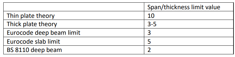
When modelling slabs, wall or bases using the Masterseries Finite Element module, the use of Mindlin-Reissner based finite elements, which uses thick plate theory, means that the lower advised limit for the span/thickness ratio of a structural element is approximately 3. Smaller than this limit the representation of the detailed stresses in these regions is highly likely to no longer be valid and alternative analysis and design methods are recommended.