MasterKey Retaining Wall Road Traffic Loading
Date: 12/10/2023
Versions: 2020.08 +
Program: MasterKey Retaining Walls
MasterKey Retaining Wall Road Traffic Loading
MasterKey Retaining wall design includes for the option to design a retaining wall as a highway loaded structure. This can be either;
- A retaining wall with a road running parallel on the retained soil side, which will be referred to as a ‘Highway retaining wall’. The highway loading will transfer through the soil creating additional lateral earth pressure on the soil retained side of the wall.
- A bridge abutment soil retaining wall supporting a bridge deck on the top of the wall and highway loading on surface of the retained soil from the road leading up to the bridge will be referred to as a ‘Bridge Abutment Retaining Wall’.
For the purposes of retaining wall design the vehicle loading is split up into two main categories. For British Standard (BD30/87 BD37/01), this is HA & HB loading. For Eurocode EN 1991-2 Traffic Load on Bridges, this is LM1 & LM3 (where LM refers to load model).
Taking the Eurocode, LM1 covers the general use case of normal traffic loading, while LM3 covers larger vertical loads referred as Special Vehicles (SV) or Special Order Vehicles (SOV). For SV/SOV loading in LM3, the loads are broken down in sets of loads from the large vehicle axles. The UK NA to EN 1991-2 outlines different axle patterns and loads for different sizes of vehicles, e.g., SV80, SV100 & SV196, where the number refers to total gross weight in tonnes of the special vehicle.
MasterKey Retaining Wall does not offer the ability to select different types of SV or SOV vehicles, but rather you are required to calculate the load and input them under the LM3 load category. A key point to note is that the design is for a unit length of retaining wall, therefore all point loads from LM3 SV/SOV axles and UDL from LM1 lanes will need to be converted to equivalent load per 1m unit length of retaining wall.
Bridge Deck Loading
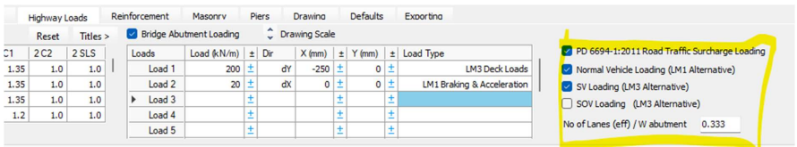
For ‘Bridge Abutment Retaining Wall’ bridge deck loading applied to the top of the wall, you should calculate the total vertical and horizontal reactions of your SV or SOV loading and input these as a ‘LM3 Deck Loading’ (vertical) and ‘LM3 Braking & Acceleration’ (horizontal) load type. You should ensure the correct direction is selected of the chosen load types. Similarly for LM1 loading.
Retained Soil Highway Loading
For ‘Bridge Abutment Retaining Wall’ and ‘Highway retaining wall’ the highway loading on the surface of the retained soil can be applied in the ‘Loads’ tab. This offers both vertical line loads (parallel to wall) and vertical full/partial area loading (with partial having a Start X1 and end X2 distances specified) on the surface of the retained soil. These loads are transferred through the soil as part of the soil pressure analysis to produce additional lateral earth pressures. The loading from LM1 or LM3 should be converted to kN/m of line loads and kN/m2 for area loads. In both cases the horizontal distances of the load from the top of the wall stem can be specified.
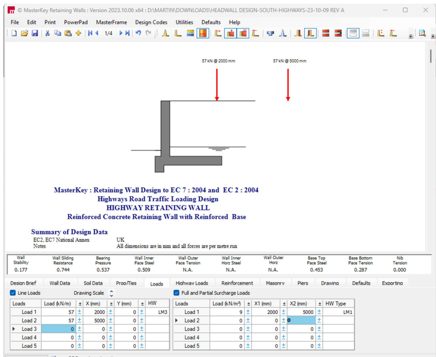
For the ‘Highway retaining wall’ this would refer to the distance of the parallel road from the top of the wall stem. For LM1 loading a partial surcharge area load would be appropriate with X1 and X2 distances specified. For LM3 a set of line loads could be used to represent loading from a line of wheels on one side of an SV/SOV axle, however an equivalent partial surcharge area loading may yield similar accuracy depending on the proximity of the road to the wall. The example below shows the case of one 3m wide lane positioned 2m from the wall stem, with SV80 LM3 loading applied through two line loads and an LM1 UDL over the lane width.
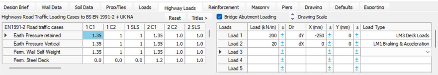
For the ‘Bridge Abutment Retaining Wall’ SV LM3 this would refer to the distance of the vertical load from the wall stem, while for LM1 loading this would likely be a full surcharge (without distances X1 & X2) specified. It is likely for the LM3 SV loading the most critical condition will be when the vehicle is at a short distance from the wall stem. In this case the LM3 SV loading and LM1 lane loading both run perpendicular to the wall, and hence is more discrete in relation the overall length of the wall. You may have a single SV load over a 3m wide length, while the wall is 10m long. How you convert these discrete loads into per m run of wall loads requires engineering judgment.
For this purpose, PD6694-1:2011 Road Traffic Surcharge Loading has proposed a simplified alternative for dealing with bridge vehicle lane loading on the surface of the soil retained side. The values of the load are fixed for Normal Vehicle loading (LM1) and SV and SOV (LM3) types. It applies the loading to the back of the wall through an equivalent top edge lateral line load combined with a full lateral UDL pressure per vehicle lane. The SV loading in this method covers SV100 and SV196, as the soil pressure produced by both vehicle is similar due the axle loads being equal (yes 196 is heavier but it is also longer and loads further from the wall on the soil retained side will have no impact on the wall). The PD comments that SV80 is less critical than normal LM1 loading (as noted in the UK NA) and is therefore ignored. If this method is used the equivalent type LM1 and LM3 line and surcharge UDL in the 'Loads' tab need not be input and should be removed.
Regards,
MasterSeries Team