Stability & Fire Boundary
Sway Stability, Snap Through and Fire Boundary Design Checks
The Sway Stability, Snap Through and Fire Boundary Design checks are displayed using the Stability & Fire Boundary button in the MasterPort side toolbar.
To apply Sway Stability, Snap Through and Fire Boundary design checks:-
You can assign up to 5 checks for each design check, and have the option to assign a brief title.
The first three input parameters are similar in all 3 design checks
- Column: Click on the Column cell in the input grid then from the frame geometry area select the column. The member number will be placed in the input cell, and the cursor will move to the next row, ie, Rafter 1 input cell.
- Rafter 1: Select the first rafter member
- Rafter 2: Select the second rafter member
Complete the remaining input data for each check.
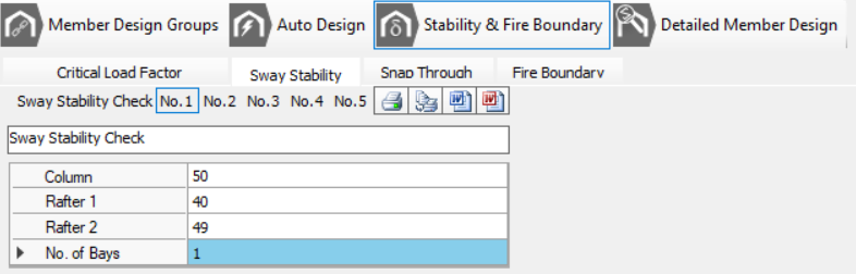
Sway Stability Check
SCI P252
This is a quick, code-style screening check on a portal frame.
See SCI P252 Section 6 – In-plane frame stability → 6.2 Sway check method → “Formula Method” and Section 6.2.2 – Sway-check method for lateral load cases
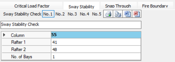
- No. of Bays: Number of portal bays.
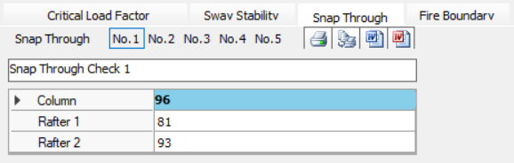
Snap Through Check
SCI P252
This is a quick, code-style screening check on a portal frame.
It is recommended to utilise the various Analysis options (such as the Elastic Critical Load Factor λcr & P-Delta) to quantify actual global stability effects in your Portal frame .
SCI P252 - the “formula method” checks in the In-plane frame stability section, specifically the snap-through stability subsection.
Fire Boundary Check
SCI P313
MasterSeries Fire Boundary Check is implementing SCI P313’s formula method (with K-factor, geometry coefficients A/B/C, residual moment and VR/HR/OTM checks).
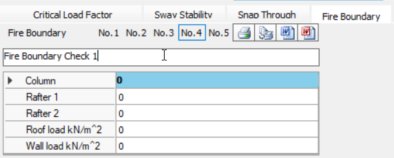
- Roof load kN/m^2: Reduced Roof Dead Load at Collapse
- Wall Load kN/m^2: Reduced Wall Dead Load at Collapse
Additional Fire Boundary Checks
The fire boundary checks will also carry though to
- Steel Connections Design module to create a base plate design check for the associated bay.
- Concrete Pad Foundation Design – The same load case transfers to the Pad/Column Base module, ensuring axial load, shear and punching checks are re-run with the reduced wall/roof dead loads appropriate to a fire scenario.
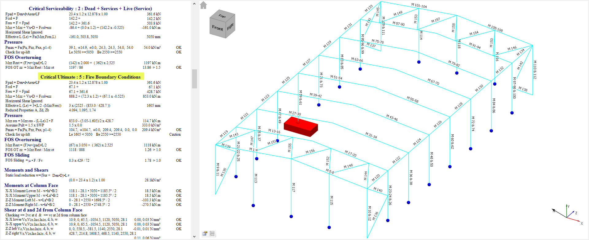
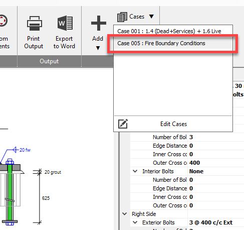
Output
The calcs will show if the particular check is passing of failing.
Printing and Exporting of these 3 design checks is carried out from within the general checks tabs at the bottom of the screen, and not in the main print manager.
.png)
.png) Print/Export the current design brief, i.e., only the active number of the active design check.
Print/Export the current design brief, i.e., only the active number of the active design check..png)
.png) Print/Export all briefs numbers (which contain data) for all 3 design checks.
Print/Export all briefs numbers (which contain data) for all 3 design checks.
Nodal Displacements
In MasterPort, the nodal displacements check is located along with the four general checks as outlined above. Displacement checks are automatically generated for sway stability, and horizontal eaves displacement on the eaves nodes, as well as vertical displacements on the apex nodes, as shown below.

Additional check nodes can be added along with the relevant load cases, displacement directions and limits if applicable. Up to 9 lines of checks can be included.
As with the general checks, printing and exporting is controlled from the nodal displacements tab and not the general print manager.
.png)
.png) Print/export the nodal displacement checks as they appear in the grid.
Print/export the nodal displacement checks as they appear in the grid.