Lateral Restraints
Purlins and Side Rails
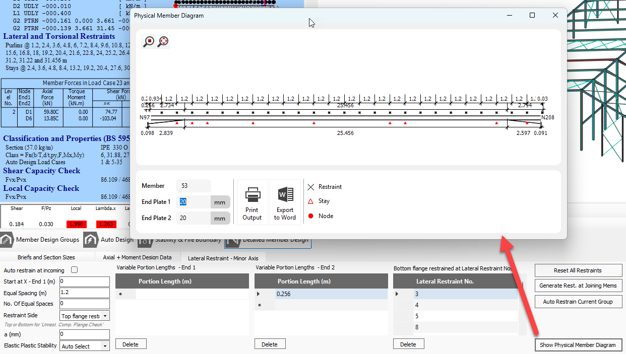
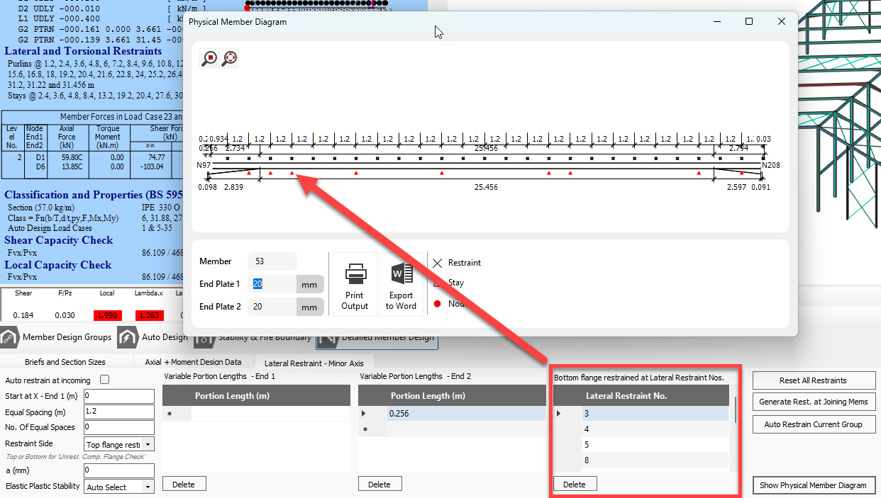
To view the lateral restraint tab, activate an Axial with Moments, or Appendix-G design brief. The lateral restraints are defined in a slightly different and perhaps more convenient manner than in MasterKey Steel. As with all input data the specified restraints apply to all members in the currently active member design group. The locations of the lateral restraints are drawn in the frame graphics area. The diagram below best describes the definition of lateral restraints.
.png)
Torsional Stability Stays
MasterPort contains some additional functions for the positioning of torsional stability stays in the Appendix G design check (or Annex B-B in EC design). When an Appendix G brief is active, the torsional restraints tab becomes visible. The positions of torsional stability stays may only be located coincident with a lateral restraint. The restraint numbers are shown in the member diagram. Stays can be added graphically in the member diagram area. With the MasterPort Stay@ button depressed, clicking on the member near a restraint position will apply a stay indicated by a black dot. To remove the stay, simply click again on the black dot.
.png)