Steel Design Toolbar
The MasterPort/MasterPort Plus design environment seamlessly integrates the analytical results into the steel design verification phase, utilising design briefs and member groups for efficiency. The design workflow generally progresses through the following stages:

Quick Overview

Member Design Groups Tab
In MasterPort Plus, the program automatically sets up and manages design groups upon entering the Steel Design module. These groups categorize structural elements into subsets (e.g., Main Portal members (M), Roof Bracing (Br), Gable Columns (G)) to apply collective design criteria efficiently.
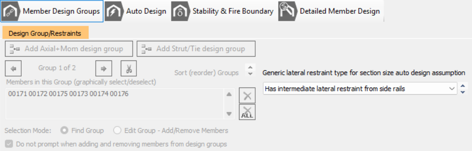
Key characteristics of Member Design Groups:
- A design group enables a single design check, such as Axial with Moments or Strut & Tie check, to be applied simultaneously to multiple members sharing the same design requirements.
- A member can only exist within one design group.
- Each group is backed by a single design brief
- All members assigned to group will have the same section size and design parameters, e.g. lateral and torsional restrain arrangements.
MasterPort Plus Simplified Interface - ON
- In interface to mange the groups is disabled as this is controlled automatically by the MasterPort
- MasterPort Plus simplified interface assigns members to group based on Portal Frame Symmetry options
MasterPort Plus Simplified Interface - OFF
- The management of the design groups (brief) can now be edited. It is vital that you ensure these group are set up appropriately as they control the final member design.
- The objective should be to add groups as appropriate and assign each member to a group. Members not assigned to group will not be designed in 'Detailed Member Design' mode.
- Note the 'Find Group' and 'Edit Group' mode. In find mode when you click on a member you a re navigated to the group is is assigned to. In edit mode you can add and remove member from the current group.
Generic Lateral restraint type setting for section auto design assumption
Affects the inclusion for buckling design in the initial automatic member sizing 'Auto design' mode.
- Has intermediate later restraints - assumes the members lateral torsional buckling is controlled by purlins/side rails and design and the auto design is limited to local member section capacity
- No intermediate restraint - auto design chooses section based on member local and unstrained buckling design.
- Lateral restraint at bottom of eaves haunch - in columns only - the automatic design is limited to the uniform portion of the column beneath the eaves haunch.
Auto Design Tab
The Automatic Design features automate the process of selecting appropriate section sizes and optimising restraint systems.
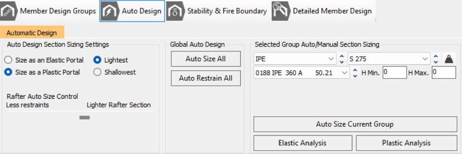
Functionality:
- Sizing: You can select to size the members as an Elastic Portal (typically checking service loads and deflections), or a Plastic Portal (determining frame behaviour under ultimate loads, aiming for an economical design by allowing plastic moment redistribution).
- Sizing can target the Lightest section (by weight) or the Shallowest section (by depth).
- The plastic sizing approach attempts to induce up to 40% over-stressing below the haunch node in exterior columns to facilitate plastic hinge formation, reflecting the best practice in portal frame design.
- Auto Restrain: The Auto Restrain All function automatically optimises the placement of lateral restraints (purlins/side rails) and torsional stability stays for all member groups based on default spacing values (e.g., roof purlins at 1.8 m centres, side rails at 1.4 m centres).
Stability & Fire Boundary Checks
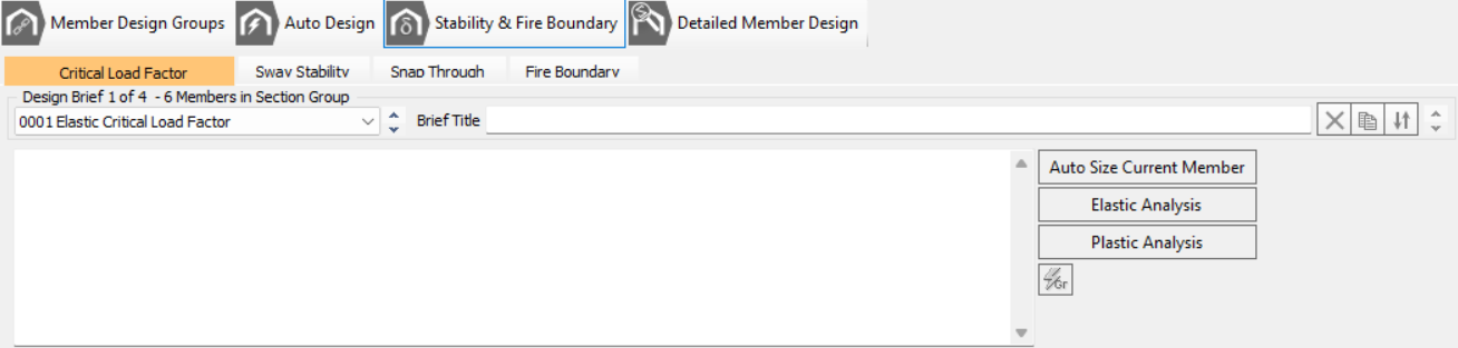
These are specialised checks displayed via the general checks toolbar button, addressing critical limit states beyond standard member verification.
- Elastic Critical Load Factor (Sway Stability): This check assesses the frame’s sensitivity to second-order effects (αcr or Alpha Crit).
- SCI Guidance: If αcr is less than 10 for elastic analysis (or αcr is less than 5 for plastically designed frames subject only to gravity loads, which is based on SCI guidance), the influence of deformed geometry cannot be ignored. You must then account for this by either enabling P-Delta analysis or relying on the software to amplify the first-order effects.
- Note: When determining αcr using buckling analysis in MasterPort, the geometric stiffness matrix components are selectively modified only for the major axis of main portal frame members (columns, rafters, beams, etc.).
- Fire Boundary Check: This assesses the column and rafters near a fire boundary for potential collapse under reduced dead loads. An extra Fire-Boundary load case is automatically generated, checking the boundary column and rafters against factored wall and roof dead loads appropriate for a fire scenario. This check automatically transfers to the Pad Foundations module to ensure column base checks are re-run with the reduced loads.
Detailed Member Design (Restraints and Verification)
This phase focuses on validating the design against specific criteria, particularly concerning lateral and torsional stability.
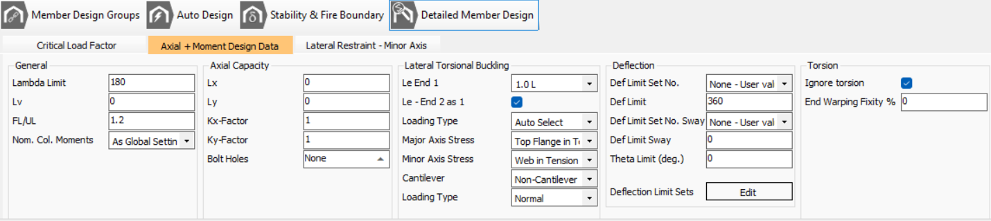
- Restraint Verification: This provides granular control over individual members within design groups.
- Lateral Restraints: The spacing of purlins and side rails dictates the lateral and torsional restraint positions used in the steel design module, which are critical for determining the buckling length for lateral torsional buckling checks (Annex BB/Appendix G). Torsional stability stays must be positioned coincident with these lateral restraints.
- SCI Guidance: When verifying member stability, careful consideration must be given to the adequacy of restraints, especially whether side rails are continuous or interrupted by openings, as only continuous elements can reliably provide restraint.
Iconology
The design toolbar and icons are found at the bottom of the frame graphics area and in the bottom design tabs.
| Move to Previous/Next design brief - member design group. |
| Edit member design groups. Add and remove members from design groups. |
| Move to Auto Size Member brief and display the Automatic Design options. If an Auto Size brief is not present one is added. |
| Display sway stability, snap through, fire boundary, and nodal displacement design checks. |
| Side Rails and Torsional Restraints (Detailed Checks). Carries out detailed checks on the lateral torsional buckling and provides access to edit the lateral and torsional restraints of the selected member. |
| Scan current view for failures |
| Step through failures detected by the scan for failures function |
| Display members maximum unity ratio (after scan for failures) |
| Display maximum unity ratio on the critical member in each section size per design group (after scan for failures) |
| Display failing members maximum unity ratio |
| Draw Plastic Hinges Formed |
| Label Plastic Hinges with Load Factor Formed at |
| Export the current design brief to Printer/PowerPad |
| Export design output to Printer/PowerPad. Select design output from all member portions to send to export. |
| Lean design tools - estimate design utilisation and identify quickly where material can be saved. |