Lateral Loads
Use the Lateral Loading options to specify wind loading and horizontal line loads. Racking in-plane moments and shears can also be included.
Out-of-Plane
Basic Loads (Wall panels)
.png)
Wx - lateral uniform area wind load (unfactored in kN/m2)
Can be applied to the whole of the face of the wall.
Qx - triangular area load (unfactored kN/m2)
Can be applied to the wall, where Qx is the full intensity of the load at the bottom of the wall, reducing to zero at the top of the wall. This option could be used to check a masonry retaining wall.
Is non-critical (reduce material factor UK NA)
If the removal of a wall panel does not affect the overall stability of a building, a reduced material factor can be used.
Limit H/L Ratio to 0.3 and 2.00
Note, this limit only applies when not using the 'Advanced Yield Line' method of lateral load analysis. In this case for two-way spanning lateral load analysis the simplified bending moment coefficient tables in the design codes (e.g. Annex E in EN 1996-1-1) limit the height over length ratio (H/L) to min and max values. By removing the tick from this option, the H/L limits are relaxed to 0.25 and 2.1 and the bending moment coefficients are calculated from yield line first principals for standard configuration two-way spanning panels. For H/L values outside these limits the wall panel or subpanel is conservatively assumed to be one-way spanning. This can be particular problematic for walls laterally only supported (not fixed) on only three edges. Take a pinned left right, bottom and free top edge wall of H = 3m and L = 7.5, hence H/L=3 meaning wall will not span in two directions. If the base where fixed the wall would span vertically as a free standing cantilever, however since it is pinned the wall must span the 7.5m horizontally, ignoring any effect from the base lateral pinned support. The 'Advanced Yield Line' avoids such limitations.
For laterally loaded stiffened walls, the piers can be in tension or compression.
Basic Loads (Masonry Columns)
For columns you can select the units for lateral loads (kN/m or kN/m2). You can also define a uniform and triangular load in each direction.
.png)
Edge Loads
.png)
Edge loads can be applied to the perpendicular to the wall. For this to work the edge fixity on the particular edge must be set to 'free' for the load to be applied. The loads are in kN/m. These could represent a lateral line load coming from another wall perpendicular to the wall being designed or a horizontal line load along the top edge.
Line Loads
.png)
Up to 10 lateral line loads can be place against the wall. These can be defined as a load in kN/m with a start point (X1 and Y1 in metres) and an end point (X2 and Y2). Thus the line load can be horizontal, vertical or inclined. A horizontal line load can represent the load applied to a wall by a racking shelves restraint system, for example.
The Out-Of-Plane line load you apply in MasterKey Masonry Design is factored during the analysis for the bending resistance design.
For out-of-plane lateral loading, which includes wind and other lateral loads like line loads, the software considers a load factor of 1.5. This factor is applied to the unfactored lateral load you input. You can read more here within 📑 EuroCode Loading Cases.
To delete a load, right mouse click on the line that load is in and the 'delete' option will appear.
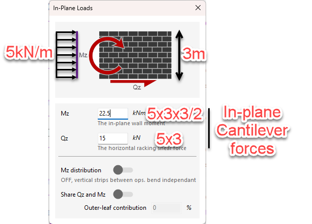
In-Plane Loads
A developed in-plane wall moment (Mz) and total horizontal racking shear force (Qz) can be applied to the wall. An example of how these forces should be applied is shown below.
For example, a 5kN/m load along the length of the wall, should be applied as follows:
- Qz: 5 x 3 = 15kN total
- Mz: (5 x 3) x (3/2) = 22.5kN.m
Mz distribution
Relates to how in-plane overturning moments are effectively shared or distributed across the vertical strips in a wall panel that contains openings.
When applying in-plane loads (racking shear Qz and moment Mz), the software must decide if the wall acts as a single composite unit or as separate, independent piers split by the openings. The Mz distribution toggle controls this behavior:
- Mz Distribution ON: The software assumes the in-plane section "remains plane". This means the wall panel acts as a single cohesive unit. The moment is shared across the entire section, implying that the masonry above and below the openings is stiff enough to transfer bending moments between the sections on either side of the opening.
- Mz Distribution OFF: The software assumes that the masonry connecting the panels (e.g., the strip above a window or door) is too flexible or weak to transfer moment. Instead, it assumes this connection only transfers horizontal shear loads (Qz) between the sections. Consequently, the vertical strips acts as two (or more) independent wall panels rather than one.
Practical Application and Engineering Judgment
The decision to turn this setting on or off depends on the geometry of the masonry around the opening:
- Small Openings: If you have a small opening, it may be appropriate to keep Mz distribution ON so that the wall acts as one solid unit.
- Large Openings (Narrow Strips): In scenarios where you may have a narrow strip of masonry above an opening (such as a door or large window), you should typically keep Mz distribution OFF. In this case, that narrow strip cannot be relied upon to transfer moment; it effectively acts as a link transferring horizontal load only.
Structural Implications
When Mz distribution is turned OFF in a wall with significant openings:
- One side of the opening may be in tension while the other is in compression, acting independently.
- The software calculates the distribution of stresses on the wall based on this "split" behavior.
- This is generally a more conservative approach for walls with large openings, preventing the software from overestimating the wall's stiffness and moment capacity by assuming composite action that doesn't structurally exist.
Share Qz and Mz
You can change the in-plane loads from being fully resisted by the inner leaf, to be shared between both the inner and outer leaves.
Outer Leaf Contribution
This refers to how the different skins of a cavity wall participates in resisting loads.
This requires Engineering Judgment. A common default is to set this to 50%, assuming both leaves share the load equally. However, you may want to proportion this based on the relative stiffness (thickness) of the leaves. For example, if the inner leaf is a 215mm block and the outer is a 102.5mm brick, the outer leaf is less stiff. In such a case, you might calculate the outer leaf's contribution to be closer to 33% rather than 50%.
To utilize this contribution, the two leaves must be adequately connected to ensure they act together to resist the overturning forces.
See Also: