Setup & Fixity
Wall Setup
The wall setup allows you to set up the masonry wall as either rectilinear or as a gable wall, either single leaf or cavity, and allows you to introduce piers to stiffen the wall or as a masonry column.
Masonry Wall:

Cavity wall: Specify if single or double leaf
A cavity wall is composed of two separate masonry walls (leaves) separated by an airspace or "cavity".
Height & Width: width of the masonry wall
Height & Width factor: A user-defined adjustment (<1.0 typically) that allows the engineer to account for structural restraints that stiffen the wall horizontally, resulting in a reduced effective length for buckling checks.
The user can decide on a factor for the effective height of a wall, column or pier and the effective length of a wall based on clauses 24.3.2 and 24.3.3 in BS 5628 Pt 1: 2005, which relate to the support conditions around the periphery of the panel.
Assumptions regarding types of lateral support which can provide simple and enhanced resistance to lateral movement can also be found in clauses 24.2.3 and 24.2.4 of BS 5628 Pt 1: 2005 for both horizontal and vertical support conditions.
Defining the Gable Geometry
The gable shape is defined by three primary inputs when setting up the wall panel. These inputs are the
- Gable H: This refers to the height of the gable measured from the top of the wall to the peak of the gable. It helps define the slope and overall profile of the gable roof.
- Asymm.: This option allows the user to create an asymmetric roof, where the two sides of the roof have different slopes or lengths. The offset from the centre can be specified to control how far the ridge is shifted from the midpoint of the building.
- Hip Flat: This option typically refers to a hip roof with a flat top section.


Stiffened Wall


For walls stiffened with piers:
Define the outstand ratios (OR1 and OR2) - "Outstand” (or “flange outstand”) is the portion of wall either side of a pier that is allowed to act compositely with the pier when the wall spans out of plane.
The outstand ratio limits cap how much of that adjacent wall you are permitted to count, the length of wall (as a ratio of wall leaf thickness) that can be considered as stiffened by the pier either side and is considered to act as the flange of a t-section where the pier is the web. The thickness t is the thickness of the leaf of the wall
typically 4 to 6 times the wall leaf thickness, to set the flange lengths on either side of the pier (as per BS 5628-1, cl 32.4.3) .
Set the distance (D0) to the centre of the first pier and the pier centres (CCP) in millimetres. If D0 = 0, the piers will be centred on the wall.
Specify the pier thickness and width.

Masonry Column

Masonry Column Geometry: Specify the breadth, thickness, and height of the masonry column, along with the effective height factors in the X and Z directions. The effective height factor is a coefficient applied to the actual column height to determine its effective height (hₑff). This parameter is essential for assessing the column’s axial capacity, particularly its resistance to buckling.
Edge Fixity
The edge fixity option allows you to define the edge fixities around all 4 sides of the wall independently.
Both the inner and outer leaves can have same fixities or Different fixities if you switch off the “Outer leaf has the same value as inner” option.


- The edge is completely restrained, preventing rotation and movement.
- The wall must crack at the supports before any rotation occurs.
- The edge provides vertical support but allows rotation, acting as a simple support.
- The edge has no restraint, allowing full movement and rotation.
- Used for movement joints or unsupported edges; the wall then behaves as a three-sided panel.
- Allows you to define an intermediate level of restraint between pinned and fixed (positive %) or pinned and free (negative %).
- Useful for modelling realistic boundary conditions where partial rotational restraint is expected.
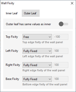
You can have both the inner and outer leafs having the same fixities or switch off the 'Outer leaf has the same value as inner' option and define the edge fixities for the outer leaf to be different than those of the inner leaf. This is particularly useful where the inner leaf is 'pinned' to a concrete frame and the outer leaf is continuous outside the concrete frame. In these sort of cases a weighted percentage fixity is applied to the wall edge in question.
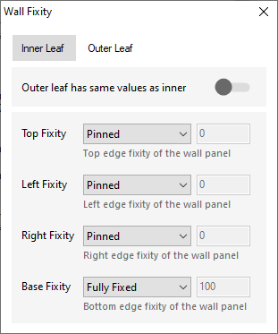
The percentages represent:
.png)
When the wall is analysed, these percentage fixities are taken into account.
.png)
You can have both the inner and outer leafs having the same fixities or switch off the 'Outer leaf has the same value as inner' option and define the edge fixities for the outer leaf to be different than those of the inner leaf.
Internal Wall Fixity (only available for AYLA )
Internal lateral restraint adds a continuous line support within the wall panel. Wall fixities represent the internal lateral supports or horizontal restraints within a wall, defined by their vertical position and always connected to the external boundary. It changes the analysis by splitting the wall’s effective height/length into sub-regions above and below the restraint, which reduces the spanning dimensions, alters bending moment distributions. It not carry vertical load; it provides lateral restraint only.
For yield line analysis, the wall is treated as continuous over these supports, causing yield lines to form on both sides and effectively dividing the wall into zones, each with its own distinct yield line pattern.


If the length input is set to zero, the restraint spans the full width of the wall. Alternatively, specific lengths can be defined from either the left or right side.