How to Model Waffle and Ribbed Slabs in MasterSeries
In MasterSeries (specifically within MasterFrame Finite Element Analysis, MasterKey Concrete Beam Design, and MasterKey Concrete Slab Design), modeling and designing waffle and ribbed concrete slabs requires careful setup to ensure accurate structural stiffness, load distribution, and reinforcement checks.
1. Recommended Modeling Methodology
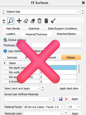
⚠️ Critical Pitfall: Do NOT Use "Ribbed FE Material"
A common mistake is selecting the "Ribbed" material option in the FE surface material properties menu. The ribbed material property in MasterSeries is formulated strictly for one-way composite steel decking profiles (trapezoidal or re-entrant metal deck). Applying this setting to a two-way reinforced concrete waffle grid or ribbed slab produces incorrect directional stiffness matrices, leading to unreliable bending moments and shear forces.
                     +-----------------------------------+
                     | MasterSeries Waffle / Ribbed Slab |
                     |        Modeling Options           |
                     +-----------------+-----------------+
                                       |
           +---------------------------+---------------------------+
           |                                                       |
           v                                                       v
+-----------------------+                               +-----------------------+
|  FE Topping Slab +    |                               | Equivalent Thickness  |
|    Attached Beams     |                               |   or Beam Grillage    |
+-----------------------+                               +-----------------------+
| • 120mm FE surface    |                               | • Fast, simplified   |
|   for structural top  |                               |   preliminary check   |
| • Line elements for   |                               | • Equivalent Ixx/Iyy  |
|   downstand ribs      |                               |   with modified self- |
| • True 3D stiffness   |                               |   weight density      |
| • Full composite      |                               +-----------------------+
|   interaction         |
+-----------------------+
Best Practice Approach: FE Topping Slab + Attached Beams
The most accurate method to model a ribbed or waffle slab is to combine 2D shell elements with 1D attached line elements:
- Model the Concrete Topping: Create a 2D FE Surface in MasterFrame representing only the thin structural topping slab.
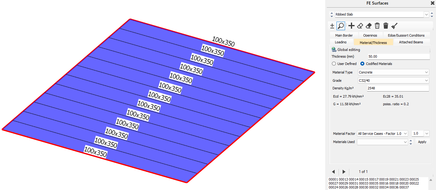
- Model Downstand Ribs as Attached Beams: Draw 1D concrete line elements along the rib paths and designate them as Attached Beams (bottom justified).
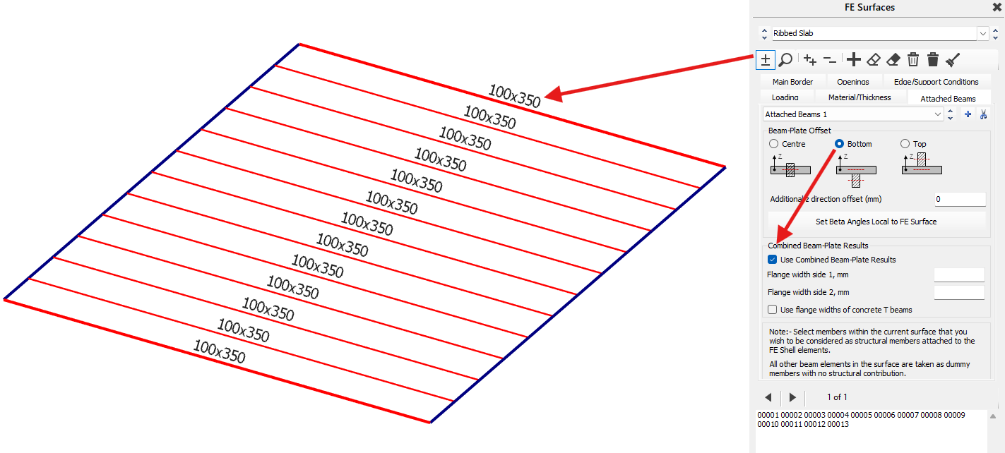
- Amend the Combined-Beam Plate Flange widths to match the flange width in the design
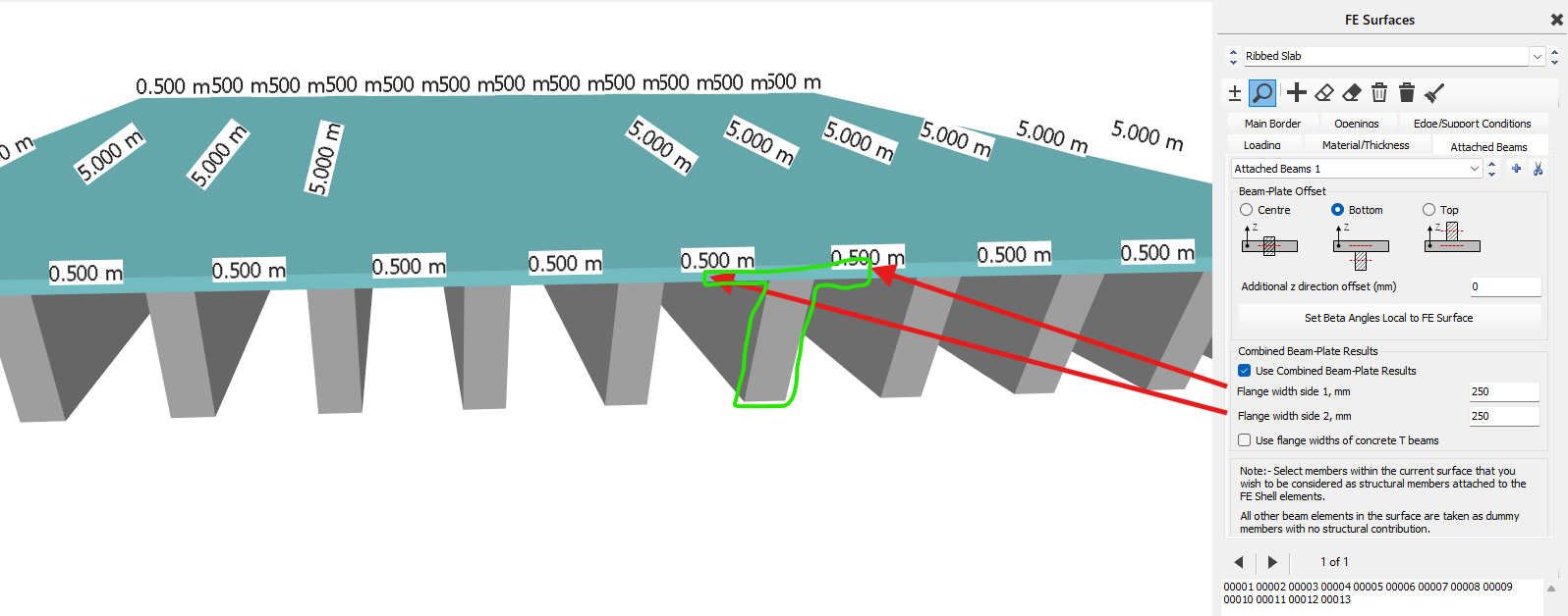
- Define Projecting Rib Depth: When defining the attached concrete beam cross-section, specify only the downstand portion projecting below the topping slab. MasterSeries automatically accounts for the geometric offset and computes the combined composite stiffness between the topping slab and the ribs.
Alternative / Simplified Approaches for Regular Layouts
- Beam Grillage Model: For preliminary sizing or regular grids, model the ribs as a 1D grid/grillage of concrete beams in MasterFrame with area load panels distributing floor loads.
- Equivalent Solid Thickness: Calculate an equivalent solid slab thickness that yields the same moment of inertia (Ixx, Iyy) as the waffle cross-section, and scale down the concrete material density to match the actual reduced self-weight of the voided profile. While approximate, this method is acceptable for early-stage design on highly regular grids.
2. Design & Reinforcement Workflow
Reinforcement design for a waffle/ribbed floor plate is split between two separate design modules:
A. Downstand Rib Reinforcement (MasterKey Concrete Beam Design)
- Ribs defined as attached beams are designed in MasterKey Concrete Beam Design.
- Enabling "Use Combined Beam-Plate Results" prompts the software to extract the integrated bending moments and axial forces from both the rib downstand and its effective concrete slab flange, designing the rib as a T-beam section.
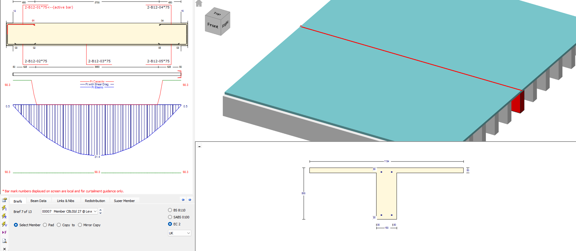
B. Topping Slab Reinforcement (MasterKey Concrete Slab Design)
- Top fabric/mesh and local reinforcement in the topping slab are designed in MasterKey Concrete Slab Design.
- Flange Area Exclusion Rule: When a slab flange width is assigned to an attached beam under Combined Beam-Plate Results, MasterSeries treats that slab area as part of the composite beam. Consequently, slab strip reinforcement cannot be generated over the beam flange width; slab design strips must be placed outside the designated flange zones.
- Independent Modules: Note that the Concrete Beam and Concrete Slab design modules operate independently, reinforcement defined in the beam module is not automatically deducted from slab mesh checks.
3. Key Software Behaviour & Practical Limitations
- FE Surfaces are Inherently Two-Way Spanning: All FE surfaces in MasterSeries analyze loads in two directions based on plate bending theory. An FE surface cannot be toggled to a pure "one-way" distribution unless it is supported strictly on two opposite parallel edges.
- Wall Supports for Attached Ribs: If attached ribs bear onto a supporting masonry or concrete wall, define a continuous edge support or wall surface in MasterFrame rather than placing discrete point supports under each rib end.
- Model Size & Analysis Time: Modeling dozens of closely spaced attached downstand beams across a large floor plate generates a high density of shared mesh nodes, which increases global stiffness matrix size and run times.
Technical Summary
| Step / Feature | MasterSeries Setting / Workflow |
|---|---|
| FE Surface Thickness | Set to topping slab thickness only (e.g. 100–120 mm) |
| Rib Section Input | Attached Beams (projecting downstand depth only) |
| FE Material Setting | Keep as Isotropic Codified Concrete (Do NOT use Ribbed) |
| Rib Design Module | MasterKey Concrete Beam Design (Combined Beam-Plate Results) |
| Topping Design Module | MasterKey Concrete Slab Design (outside attached flange zones) |