Applying Wind Panels – Automatic and Manual Generation & Troubleshooting
Overview
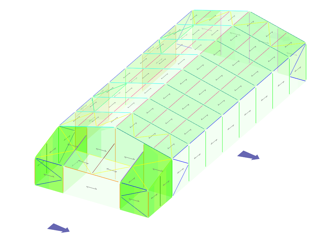
If you are unable to add wind panels to other sections or facades of your structure in MasterSeries, this is typically related to how wind panel groups are defined, the geometry of the model, or the members forming the panel boundary.
This guide explains the most common causes and how to resolve them.
1. The Wind Group Is Limited to a Single Planar Surface
The issue
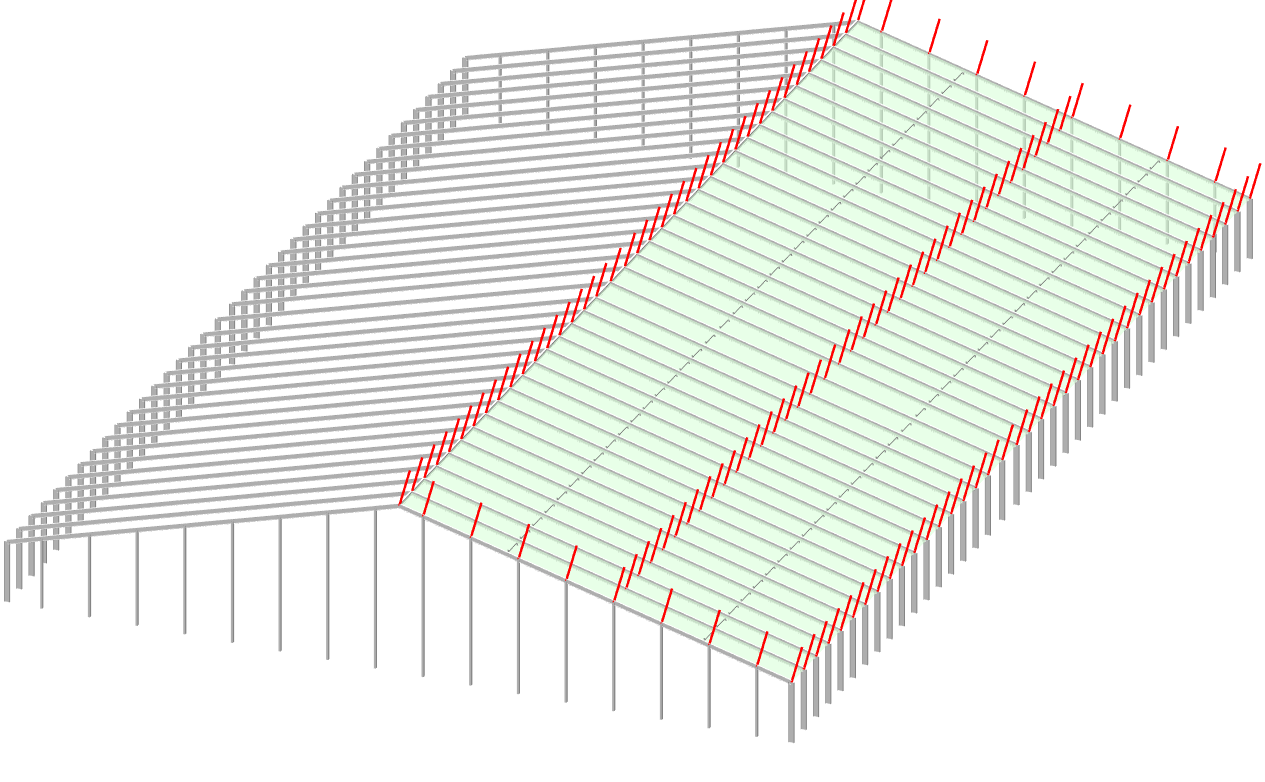
Each wind panel group in MasterSeries is restricted to a single planar surface.
For example, if you are currently editing a wind panel group for the South Face and attempt to select members on another elevation, facade, or roof slope, MasterSeries will prevent you from adding them to the existing group.
This prevents the creation of wind panels that are twisted or non-planar.
The solution
To add wind panels to a different plane:
- Open the Wind Panel side menu.
- Click Add New Group (+).
- Select the members or panels that form the new wind panel.
- Repeat this process for each additional facade or plane.
Alternatively, use Fast Select  mode. This automatically creates a new wind group when elements on a different plane are selected.
2. Open Sides or Missing Boundary Members
The issue
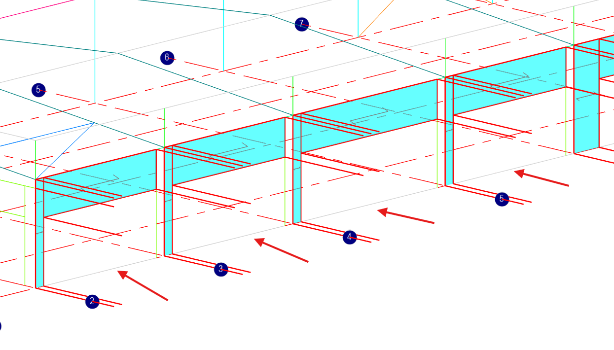
A wind panel must be enclosed by a valid perimeter. The panel boundary generally needs to consist of three or four straight sides.
If one or more sides of the intended panel are missing, MasterSeries may be unable to identify the area as a valid wind panel.
Common examples include:
- A missing column
- A missing eave or perimeter beam
- An open ground-level boundary
- A missing member between two panel corners
The solution
If the structure does not contain a suitable structural member to close the panel boundary, you can use Dummy Members.
To add a dummy member:
- Right-click in the model space.
- Select the option to insert a Dummy Member.
- Position the dummy member along the missing panel boundary.
- Ensure the member connects to the appropriate end nodes.
- Re-attempt the wind panel selection.
Dummy members are non-structural elements used to define panel boundaries and can transfer the area wind load directly to their end nodes.
3. Bracing Members Are Being Used in the Panel Perimeter
The issue
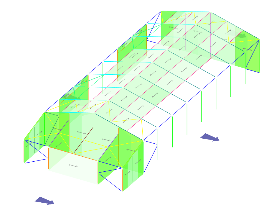
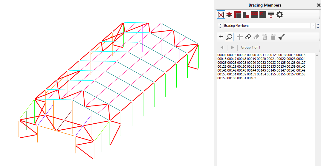
Members designated as structural bracing cannot be used to carry direct wind or area loading.
If a member forming part of your intended wind panel perimeter is classified as a bracing member, MasterSeries may prevent the panel from being created correctly.
The solution
Check the members around the perimeter of the proposed wind panel.
The perimeter should be formed using:
- Regular structural members, or
- Dummy members where appropriate.
If there are bracing members inside the panel, make sure they are correctly designated through the Bracing Members menu.
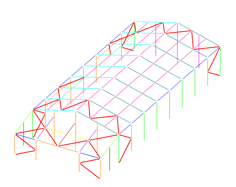
This allows MasterSeries to recognise them as internal bracing rather than treating them as part of the wind panel boundary.
4. Member Geometry Is Not Properly Connected
The issue
Members can sometimes appear connected visually while remaining disconnected in the analytical model.
For example, two members may appear to intersect on screen, but their analytical geometry may not contain a common node at the intersection.
When this happens, MasterSeries may be unable to recognise the complete boundary of a wind panel.
The solution
Use the model clean-up tools to check and correct the analytical geometry:
Modify Geometry > Check and Modify Analytical Model > Model Auto Connect and Clean Up
This can resolve common connectivity issues and ensure that intersecting members are correctly connected in the analytical model.
After running the clean-up process, try creating the wind panel again.
5. The Geometry Is Non-Planar or Curved
The issue
Wind panel groups must be defined on a single planar surface.
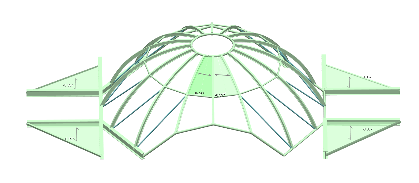
As a result, complex geometry such as:
- Domes
- Curved roofs
- Multi-directionally curved surfaces
- Twisted grids
- Other non-planar structures
It cannot generally be represented as one continuous wind panel.
The solution
Break the curved or non-planar geometry into a series of smaller flat, planar facets.
Where necessary, use dummy members to frame the individual facets.
Each planar facet can then be defined as its own wind panel group.
For example, instead of attempting to create one wind panel across a curved roof, divide the roof into several flat sections and create a separate wind group for each section.
Quick Troubleshooting Checklist
If you cannot add a wind panel to another section of your structure, check the following:
| Check | What to look for |
|---|---|
| Wind Group | Is the new panel on a different plane or facade? If so, create a new group. |
| Panel Boundary | Does the panel have a complete 3- or 4-sided perimeter? |
| Missing Members | Is a column, beam or other boundary member missing? |
| Dummy Members | Can a dummy member be used to close an open boundary? |
| Bracing | Is a perimeter member designated as a bracing member? |
| Connectivity | Are all intersecting members properly connected analytically? |
| Geometry | Is the proposed panel completely planar? |
| Curved Surfaces | Does the surface need to be divided into smaller planar facets? |