Viewing and Interpreting FE Line Support Reactions
When a finite element surface is supported along an edge using a line support, the resulting reactions are calculated at the finite element nodes. These reactions can be viewed in MasterFrame, but care is required when interpreting them as an equivalent distributed reaction along the supported edge.
Viewing FE Line Support Reactions
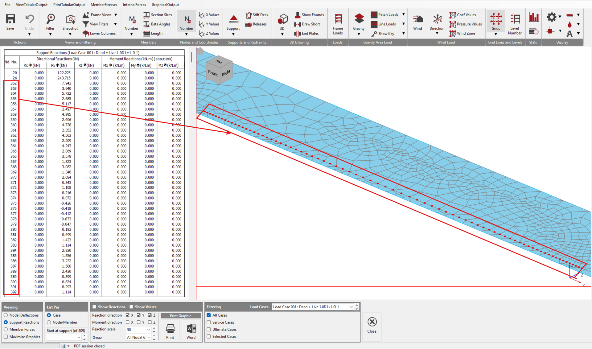
By default, the Nodal Support Reactions view selects only the Basic nodes in the model. Nodes created exclusively as part of the finite element mesh are therefore not automatically included.

To display the reactions along an FE supported edge:
Display the Nodal Support Reactions results.
Use Window Select to select the nodes along the required FE line support.
The reactions at the selected FE nodes will then be displayed.
These results are nodal reactions, rather than distributed line reactions.
Why the Nodal Reactions Cannot Be Directly Converted to a Line Load
For a quadrilateral finite element, the mid side node attracts a greater proportion of the load than the corner nodes due to the polynomial formulation of the element. For the three nodes along an element edge, the load is typically distributed in the ratio:
0.1667 / 0.6667 / 0.1667
rather than the simple linear distribution:
0.25 / 0.50 / 0.25
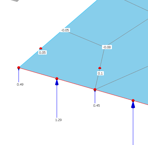
As a result, converting nodal reactions into equivalent distributed line loads is not straightforward. It requires consideration of:
- the length of each finite element edge;
- whether the node is a corner or mid-side node;
- contributions from adjacent elements; and
- the finite element interpolation used to distribute the load.
Simply dividing a nodal reaction by an assumed tributary length may therefore give an incorrect representation of the support reaction.
Why a Distributed Line Support Reaction Is Not Reported Directly
Another difficulty occurs where both distributed loads and point loads act on an FE surface supported along an edge.
Both loading types ultimately contribute to the nodal support reactions. Once these have been resolved into reactions at the FE nodes, there is no straightforward way to separate the reaction into:
a distributed line reaction; and
individual point load reactions.
For this reason, the support reaction results are presented as nodal reactions rather than automatically being converted into an equivalent distributed line reaction.
How to Obtain Support Reactions for a Line Restraint in MasterSeries
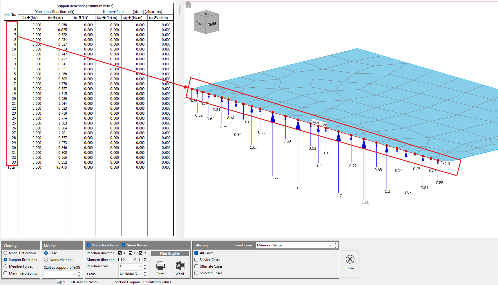
- Open Tabular Results and select Support Reactions.
- Using the selection window, select the nodes along the required line restraint.
- The table will display the support reactions at each selected node.
In the finite element model, a line restraint is represented by a series of individual nodal supports. Therefore, the reaction on the line restraint is obtained by summing the reactions at all nodes along that restraint.
The sum of the reactions in the Y-direction (Ry) represents the total vertical reaction force (kN) acting on the selected line restraint for the chosen load case. This total reaction can be used directly for design checks, load take-down calculations, and verification purposes.
Note:
Please note that the Total displayed at the bottom of the output includes all support nodes in the model and therefore cannot be used for the reaction of an individual line restraint.
To obtain the total reaction for a specific FE line support:
- Go to Print Tabular Output > Support Reactions.
- Manually select all nodes that make up the FE line support.
- Print the results to Word.
- Copy the table into Excel and convert the values to numbers if required.
- Use the Excel =SUM() function to calculate the total reaction from the selected nodes.


Development is currently investigating the possibility of removing the manual processing step. At present, the workflow creates a separate worksheet for each load case, which can become time-consuming when working with a large number of load cases.
Alternative: Review the Slab Shear Forces
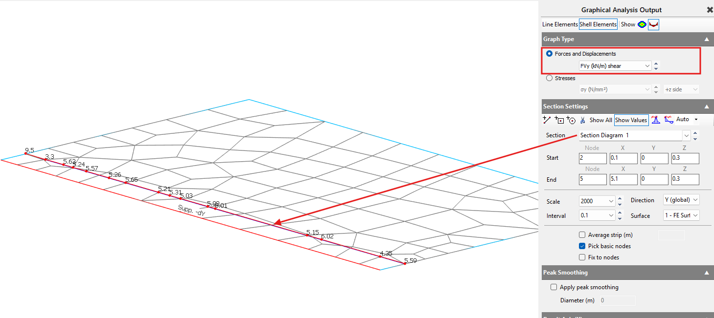
Where the load transferred along the supported edge is required, the FE slab shear force results can provide an alternative means of assessing the load transfer.
For example, depending on the orientation of the FE surface, the relevant Fxy or Fvy shear force may be reviewed.
A section diagram should be taken approximately one element away from the supported edge on either side, with the appropriate results combined to determine the total load transferred along the edge.
Avoid sampling the section diagram directly on the supported edge. Result averaging at the boundary can reduce or obscure the peak shear values occurring at this location.
Where an FE Wall Is Modelled Below the Slab
Where the supporting wall is included explicitly in the finite element model, the load transfer can be reviewed more directly.
For example, if an FE wall is modelled beneath the slab and the wall has a line support at its base, an Fy axial force section diagram taken along the base of the wall can provide a useful representation of the load being transferred through the wall.
This will generally provide a closer representation of the required wall loading than attempting to convert individual slab edge nodal reactions into a distributed line load.