Auto-Generation of Load Cases
To reduce the amount of work required in setting up the numerous load cases applicable to your model, MasterSeries has an Automatic Load Case Generator. This is used to create or edit all loadcases.
For video guidance, visit 🎥 📺MasterFrame Automatic Load Case Generator
To start the process click on the Auto generate or update Load Cases button 
This opens up the load case generator templates box.
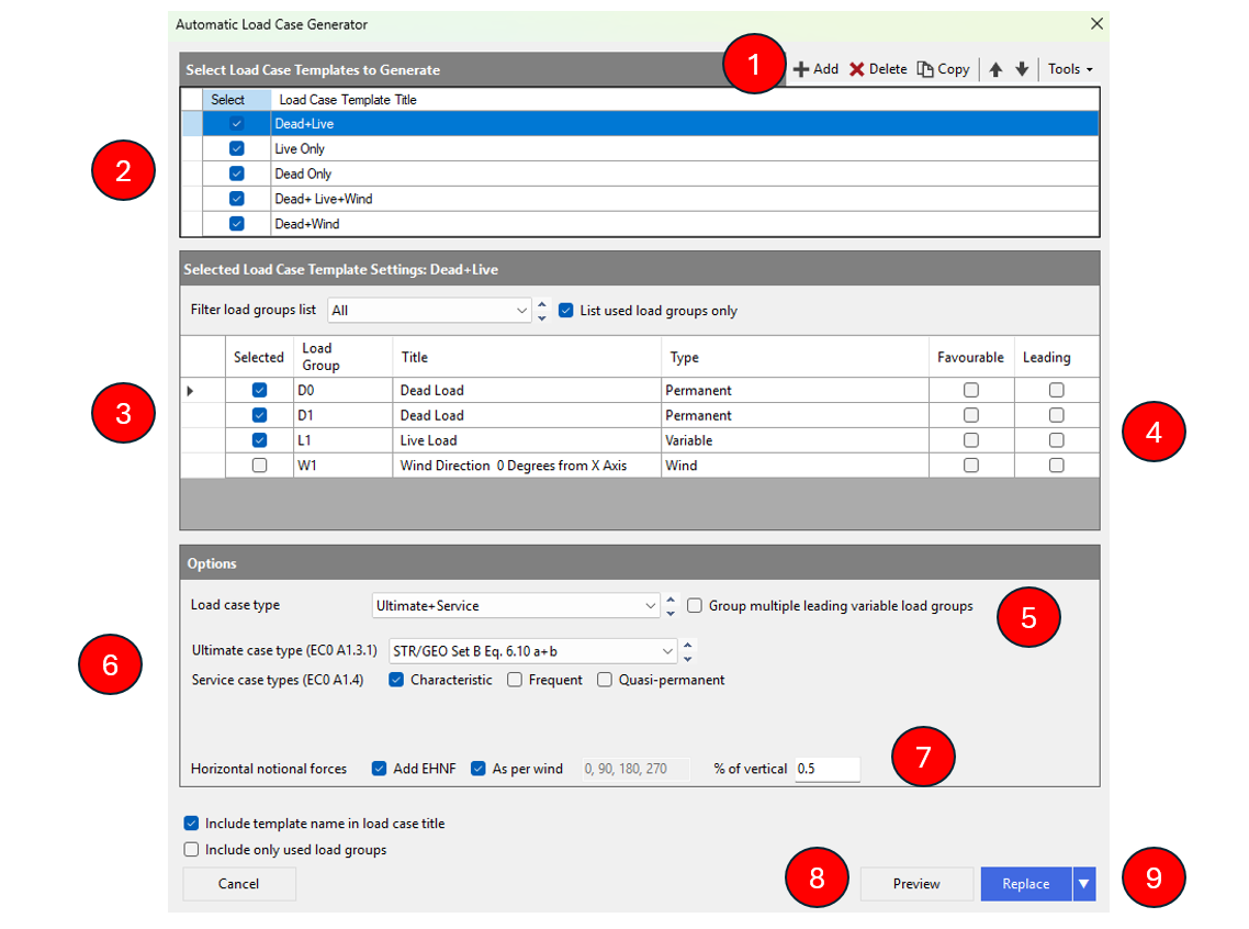
1. Top Right Tool Bar
Add
This command allows you to create a brand new load case template from scratch, which can then be configured with specific load groups and factors.
Delete
This is used to remove the currently selected template or specific items within the generator list that are no longer required for the project.
Copy
This duplicates an existing template. It is highly useful for rapidly creating similar load combinations; for example, you might copy a "dead plus live" template and then modify it to create a "dead plus snow" template.
Tool Strip
This refers to the horizontal command bar itself, which houses these icons and menus, providing a rationalised and responsive interface for navigating generator functions.
Tools Menu
This dropdown contains advanced configuration and file management options:
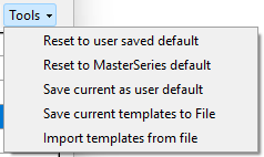
Reset to user saved default
Reverts the current generator configuration to a state previously defined and saved by the user as their preferred starting point.
Reset to MasterSeries default
Restores the generator to its original factory settings, removing user customisations and reverting to the standard out-of-the-box templates.
Save current as user default
Saves the current set of templates and factors so they become the standard default every time you start a new project in that module.
Save current templates to file
Exports your custom load case templates to an external file. This is useful for creating backups or sharing successful loading patterns with colleagues.
Import templates from files
This allows you to load templates from external files into your current project. This can be done from files you have previously saved or from the provided MasterSeries library of common loading scenarios (such as standard Eurocode or British Standard combinations).
2. Load Case Templates
Load case templates are predefined sets of rules used by the automatic load case generator to systematically create all required load combinations for a project.
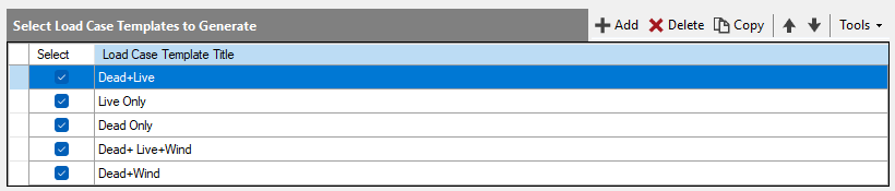
Instead of manually entering factors for every combination, you select a template that automatically identifies relevant load groups (e.g., dead, live, wind, snow) and applies the correct combination factors according to the chosen design code, such as the Eurocodes or British Standards.
Defined Load Case Templates
Dead plus Live
Generates combinations of permanent and variable actions for both Ultimate Limit State (ULS) and Serviceability Limit State (SLS).
Live Only / Dead Only
Creates cases for assessing the structure under single load types, typically for specific serviceability or characteristic checks.
Dead plus Wind / Dead plus Snow
Specifically targets environmental and lateral loading scenarios.
Uplift
A template designed to check frame stability and uplift, typically using a permanent load factor of 1.0 (favorable) combined with wind loads.
3. Primary Load Group Types
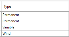
Permanent (Dead) Loads
Represented by 'D' (e.g., D0, D1). These are actions that are constant throughout the life of the structure, such as the self-weight of the members and slabs. In Eurocode design, permanent loads are not patterned because they are always present.
Variable (Imposed/Live) Loads
Represented by 'L' (e.g., L1, L2). these are temporary loads from occupancy, furniture, or moveable partitions. These are frequently patterned (alternated between spans) to find the most critical sagging and hogging moments.
Wind Loads
Represented by 'W' (e.g., W1, W2). These are lateral loads generated from site-specific wind analysis. They can be combined with internal pressure or suction scenarios.
Snow Loads
Represented by 'K' (e.g., K1). These are environmental variable loads. The generator handles these specifically, often requiring patch loading to account for drifted snow buildup against parapets or in valleys.
4. Favourable and Leading
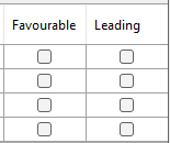
Favourable (vs. Unfavourable)
This setting is primarily used for structural stability checks, such as assessing uplift or overturning. A load is "favourable" if its presence helps stabilise the structure (e.g., the self-weight of a building resisting wind uplift). In Eurocode design (ULS), permanent loads (Dead loads) considered favourable are typically assigned a factor of 1.0 (unfactored). When a load is "unfavourable" (acting to destabilise the structure or increase stress), it is assigned a higher factor, such as 1.35. The generator creates specific cases, often for Eurocode Set A (EQU) combinations, where permanent loads are treated as favourable to ensure critical stability limits are met.
Leading (vs. Accompanying/Trailing)
In combinations involving multiple variable actions (e.g., Live load, Wind, and Snow acting simultaneously), the Leading variable is the primary action dominant for that specific case. The software allows you to designate a specific load group as the "leading" variable for a template. For instance, in a "Dead + Live + Wind" case, you might specify Live as leading, meaning it is considered the primary threat for that combination. The leading variable is assigned its full partial safety factor (typically 1.5 for ULS).
Any additional variable loads in the same combination are treated as Accompanying (or Trailing) and are assigned reduced factors (using ψ factors, such as 1.05) because it is statistically unlikely for all peak variable loads to occur at the exact same moment. If multiple variable load groups must be considered leading together (e.g., L1 and L2 across a full slab), they must be grouped to ensure they both receive the full 1.5 factor rather than one being reduced.
5. Load Case Type
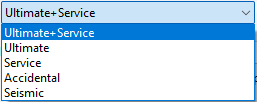
Ultimate + Service
This option allows the generator to create both Ultimate Limit State (ULS) and Serviceability Limit State (SLS) combinations in a single automated process. This ensures that the structure is checked for both peak load safety and everyday performance criteria.
Ultimate
This type generates load cases for Ultimate Limit State (ULS), which are used to verify the structural strength and stability of members. These cases apply full partial safety factors to ensure the building remains in equilibrium and does not collapse under maximum predicted forces.
Service
This type generates Serviceability Limit State (SLS) cases used to check performance criteria such as deflections, crack widths, and vibrations. Factors for these cases are typically taken as 1.0 (unfactored) to reflect the structure's behaviour under normal working conditions.
Accidental
These are often associated with Equilibrium (EQU) cases, such as Eurocode Set A, used to check structural stability against overturning and uplift. This type can also include specific loads for justifying structural robustness and preventing disproportionate collapse, such as applying a 35 kN/m² patch load to key transferring elements.
Seismic
This type is used for dynamic and seismic analysis, calculating the structural response to earthquake forces. It is a specialized analysis type typically required for projects in regions with high seismic risk.
6. Ultimate and Service Case Types
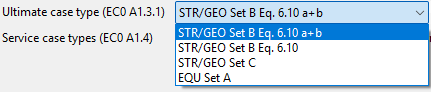
Ultimate Limit State (ULS) Types
STR/GEO Set B Eq 6.10
This is the standard combination set used for designing structural members and performing standard geotechnical checks. It follows the Action A1 and Material M1 approach, where loads are factored and soil properties remain unfactored.
STR/GEO Set B Eq. 6.10 a + b
A more refined design approach that employs Eurocode Equations 6.10a and 6.10b instead of the singular 6.10. This method analyzes two separate scenarios for each combination to potentially yield a more economical material design.
STR/GEO Set C (GEO)
Used specifically for geotechnical design (Combination 2), this type is often critical for checking soil bearing capacity. It uses the Action A2 and Material M2 approach, where the loads are less heavily factored, but the soil properties themselves are factored (reduced).
EQU Set A
Also known as Equilibrium cases, these are used for checking the stability of the structure against overturning and uplift. These cases apply "favorable" factors (typically 1.0 or less) to permanent loads to ensure the most critical stability check is performed against lateral forces.
Serviceability Limit State (SLS) Types

Characteristic
The standard serviceability check used to assess instantaneous deflections, vibrations, and general performance. These cases typically use a factor of 1.0 for all loads to reflect the structure's behavior under normal working conditions.
Frequent
Used for serviceability checks where the load occurs often, such as for dynamic analysis or crack width control. It utilises specific ψ (Psi) factors to represent a common loading scenario that is statistically likely to repeat.
Quasi-permanent
Essential for calculating long-term structural effects like creep, shrinkage, and long-term deflections. This type applies specific reduction factors (e.g., 0.3 for variable occupancy loads) to represent the portion of the load that is considered to be permanently present throughout the life of the structure.
7. Horizontal Notional Forces

Add EHNF
This is a toggle or checkbox that, when selected, instructs the software to automatically include Equivalent Horizontal Notional Forces in the generated load combinations. These forces are used to simulate the effects of structural imperfections (such as a frame being slightly out of plumb) and are a requirement for stability checks in both Eurocode and British Standards.
As per wind
This setting specifies the direction in which the notional forces should be applied. When this option is used, the software applies the horizontal notional forces in the same principal directions as the defined wind loads for the project. This ensures that stability is assessed in all axes where lateral actions are expected to occur.
% of vertical
This defines the magnitude of the notional force. It allows the engineer to specify the horizontal load as a percentage of the total factored vertical loads present in any given load combination. For example, while Eurocode 1 might suggest 0.5% for certain stability checks, preliminary or conservative estimates may sometimes use a generic figure like 3% of the worst-case vertical load.
8. Preview

The Preview function allows you to "scan through" a list of all potential load combinations the software has generated based on your selected templates. This gives you the opportunity to verify factors (such as leading vs. accompanying variables) and ensure the combinations "look good" before they are officially added to the project.
9. Existing Cases
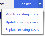
Replace existing cases
This is the most common action taken after the generator has created a new set of combinations. It wipes the project’s current load case list entirely and replaces it with the combinations shown in the preview pane.
It is used to ensure the project has a clean, code-compliant set of combinations, removing any legacy cases or manual entries that may no longer be relevant after a layout or code change.
Using this option ensures that only the cases required by the currently selected templates (e.g., Eurocode STR/GEO Set B) are present in the model.
Add to existing cases
This option appends the newly generated combinations to the end of your current load case list. It is useful when you already have a set of manually defined load cases or specialized loading scenarios in your project that you do not want to delete. For example, if you have manually created a unique accidental load case and then decide to use the generator to add standard wind combinations, "Add" allows both to coexist.
Update existing cases
This function attempts to synchronise factors between the generator and the cases already in the project. It identifies cases with matching names or IDs and updates their combination factors (e.g., changing a dead load factor from 1.35 to 1.4) while keeping unique or manually modified cases intact. This is the ideal choice if you have made a global change to your design code or PSI (ψ) factors and want to apply those changes to your existing model without losing any custom cases you may have added previously.