Web Openings Tab
Individual and multiple openings can be added to a beam. These openings can be circular, rectangular, or elongated, end notches are also possible. Openings can be positioned at any acceptable height within the depth of the web, and edge stiffeners can be added to the top and bottom of the opening if required.
Note that these openings do not have any effect on the overall depth of the beam (unlike the cellular beam option where the beam section depth will increase when openings are added).
.png)
.png)
Circular and Rectangular Openings Definitions
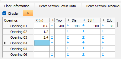
R (repeat) - 
A function for equally spaced openings where the user defines the first, second, and last locations, and the software automatically generates all intermediate openings.
Openings
This lists the individual opening identifiers (e.g., Opening 01, Opening 02) within the current set.
X (m)
The dimension (m) from the start of the beam to the centre of the opening.
Top (dimension)
The vertical distance (mm) measured from the top of the beam flange down to the top of the opening.
Dia (diameter)
The diameter (mm) of a circular opening.
Dep (depth)
The vertical depth (mm) of a rectangular or elongated opening.
Wid (width)
The horizontal width (mm) of the rectangular opening.
Stiff (stiffeners t&b)
The area (mm²) for the top edge stiffener, the software applies the same area to the bottom stiffener, and from the area provided will create stiffeners which have a compact cross-section.
Edg (edge)
The specified distance (mm) from the edge of the opening to the stiffener.
Elong (elongated type)
Inputting 'Y' (yes) designates the opening as an elongated type.
Add Circular Openings (Quick Editor)
This tool provides a rapid method for generating multiple equally spaced openings. The 'Add' button
Start @ No.
The starting index number for the new openings in the table.
Start @ (m)
The distance (m) from the start of the beam to the centre of the first new opening.
Number to Add
The total quantity of openings to be generated by the editor.
Spacing (m)
The on-centre distance (m) between each of the generated openings.
Add opening starting at current row (replacing existing data)- 
This button automatically generates the defined number of openings based on the start distance and spacing.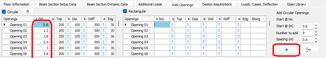
Insert opening starting at current row - 
This function (represented by the insertion icon) allows the user to insert new opening rows into the table at the current cursor position.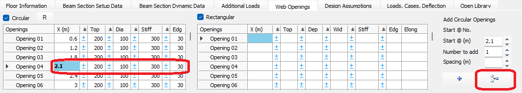
Add rectangular or elongated openings starting at current row (replacing existing data)- 
Again using the 'Add Opening' button to generate rectangular and elongated openings based on the start distance and spacing.
Add an end notch (bottom only)
Rectangular openings can be used to create end notches in a beam.
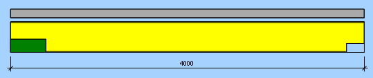
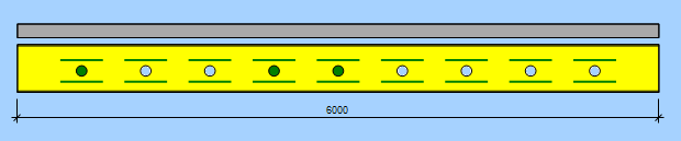
Colour Key for Openings
The colour of each opening provides specific information about the opening, as follows,
- Red - means a stress failure has occurred at the opening.
- Blue - means a dimensional failure has occurred at the opening.
- Green - all design checks have passed, and a detailed output has been provided in the calculation.
- White - all design checks have passed, and a summary calculation output has been provided.
.png)
Note
When a blue dimensional failure is shown, the opening should be moved in the direction of the yellow circle outline.
- The opening on the extreme left end of the beam above is too close to the beam end and needs to be moved to the right.
- The opening under the point load needs to be moved away from the point load.
- The third blue opening on the right side of the beam is too close to the bottom of the beam and needs to be moved up.
Full calculations are provided for the (green coloured) critical openings, where there is maximum moment or maximum shear, and summary calculations are provided for the (white coloured) non-critical openings.
References
The openings are checked against the relevant British and EuroCode design standards and other technical publications, particularly SCI Publication P355 - Design of Composite Beams with Large Web Openings.
Old Manual
Circular Openings
Method 1.
- X (m): distance from the start of the beam to the centre-line of opening
- Diameter (mm)
- Top offset (mm): distance from the top of the beam to the top of the opening
- Stiffener area (mm²) for the top plate (the same area is applied at the bottom)
- Stiffener setback (mm): distance from the opening edge to the stiffener
The calculations will suggest suitable stiffener sizes (single or double sided plates).
Method 2.
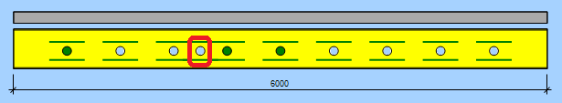
For a series of equally spaced openings a quick method can be used. Rather than entering all the individual openings dimensions, you can specify the first and second opening distances and the last opening location. Then press the 'R' button and the program will automatically add all the intermediate openings based on the spacing between the first and second entries until it reaches the last opening location.
.png)
.png)
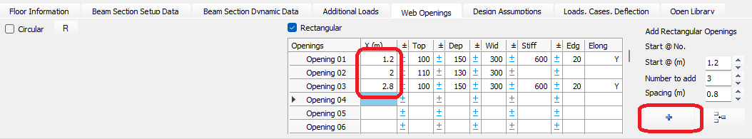
Method 3.
Another quick method of adding equally spaced circular openings is shown below. Define the start distance, the number of openings to be added and their spacing. Then press the '+' symbol to automatically add these openings.
.png)
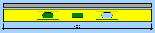
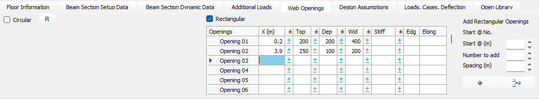
Rectangular and Elongated Openings
Rectangular and elongated openings can be added in the same way as for circular openings using methods 1 and 3 from above.
For an elongated opening place a 'Y' in the Elongation column.
.png)
.png)
End Notches
End notches on beams can be considered too. Specify the distance to the centre of the length of the notch. Add a 'Top' dimension - this is the distance down from the top flange of the beam to the top of the notch. Note that the size of the notch is not controlled by the depth and width entries in this case. Stiffener areas can be added if required.
.png)
.png)
Graphical Colours of Openings
The colour of each opening is significant. There are 4 possible coloured backgrounds to the openings.
Red - a stress failure at the opening.
Blue - a dimensional failure at the opening.
Green - passing all checks and detailed output provided in the calcs.
White - passing but only a summary calc is shown in the calcs for these particular openings.
When a blue dimensional failure is shown, the opening should be moved in the direction of the yellow circle outline.
For example, the opening at the left hand end of the beam below is too close to the end and needs to be moved in-board.
The second opening is too close to the point load and needs to be moved laterally away from the point load.
The third blue opening is too close to the bottom of the beam and need moved upwards.
With the passing openings (green and white backgrounds) full calcs are shown for the critical openings where there is max moment or max shear (green) and summary calcs for the non-critical openings (white).
References
The openings are checked against the relevant British and EuroCode design standards and other technical publications, particularly SCI Publication P355 - Large Web Opening Design in Composite Beams.