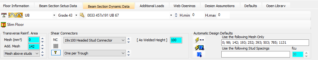
Beam Section Dynamic Data
On the Beam Section Dynamic Data tab you can define the steel details along with stud and reinforcement information.
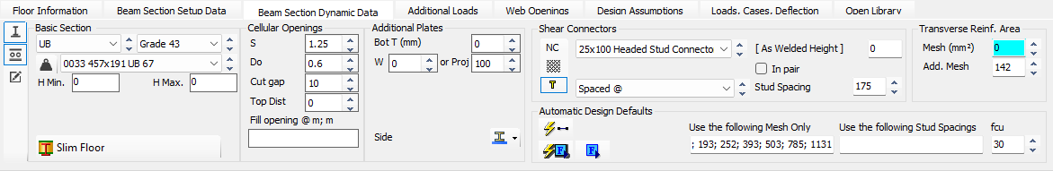
Basic Section
The Basic Section refers to the initial steel section type (eg. UB, UC, RHS, or Channel) and its size and grade selected from the library before any composite properties are applied. It serves as the primary structural element which can then be combined with a concrete slab to form a composite member.
Additional Plates ( )
)
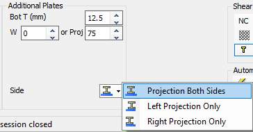
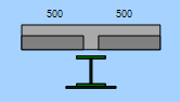
Additional Plates are components used to create compound sections by adding a plate, typically to the bottom flange of a steel beam. The user specifies the plate's thickness and width (or projection distance), and it can be positioned centrally on the beam or offset to the left or right.
Bot T (mm)
Thickness (mm) of additional bottom plate to be welded to the bottom flange.
W
Overall width (mm) of additional bottom plate to be welded to the bottom flange (governs if > 0).
Proj
Projection (mm) of additional bottom plate from the edge of the bottom flange, can be set to project from both sides, left only, or right only. (Will be ignored if an overall width > 0 has already been set)
It is important to note that a member cannot be defined as a composite beam if it has a top plate or top channel on an I-section.
Cellular Openings ( )
)
Read more 📄 Steel Sections
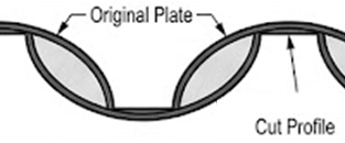
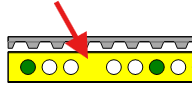
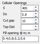
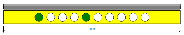
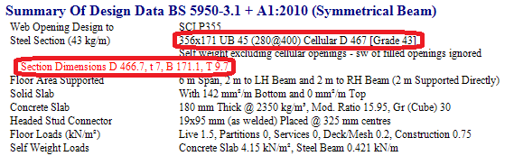
Cellular Sections are created by profile cutting a standard beam along the length of its web, moving the sections laterally, and welding them back together to form a 'new' deeper beam with regular circular openings. The geometry is defined by the cell diameter (Do) and spacing (S).
S
Cellular hole spacing can be entered directly in mm, or as a ratio of the hole diameter (up to 1.95).
Do
Cellular hole diameter can be entered directly in mm, or as a ratio of the steel beam depth.
Cut gap
As the section is ribbon cut, the cut width (gap) will reduce the overall depth achieved.
Top Dist
Distance from top flange to top of cellular hole (zero or blank will place hole centrally).
Fill opening
A semicolon separated list of hole dimensions (m) along the beam to be filled/removed.
For these members, adjustments to bending stiffness and shear deflection are made during the analysis stage.
Discrete Web Openings ( ) refer to individual or multiple openings, such as circular, rectangular, elongated, or end notches, that are added to a beam's web. Unlike cellular sections, these openings do not increase the overall depth of the beam section. While they are not accounted for in MasterFrame analysis deflections, the necessary deflection adjustments are calculated within the composite design module.
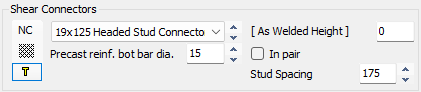
Shear Connectors
Non-Composite - 
Selecting this option treats the beam as a standard steel member within the composite module. This is often used for short-span edge beams where it is not possible to provide enough shear studs to effectively transfer the load into the concrete.
Raised Rib Pattern - 
This option is typically used for Asymmetrical Slimflor Beams (ASBs) in slimfloor construction. The pattern on the top flange surface transfers load from the beam to the concrete slab in place of, or in addition to, standard shear studs.
Shear Studs - 
These are mechanical connectors (typically 19mm diameter headed studs) welded to the top flange to enable the steel and concrete to act together as a single structural member. They are designed to transfer longitudinal shear forces and limit slip between the two materials.
Shear Stud Selection
Select the shear stud connector to be used from the drop down list. This list can be updated from within the Open Library tab.

Precast reinf. bot bar dia. - 
Specific to composite beams formed with hollowcore units and designed to British Codes, this transverse reinforcement will influence the confinement of the shear stud connectors and thus impact the reduction factor 'k'. See SCI Publication P287 Clause 4.4.3 for a full explanation.

As Welded Height (mm)
This is the actual finished height of the shear stud after it has been welded through the decking or directly to the beam.
Design codes specify minimum heights such as:
- 35mm above the deck troughs for British Standards or
- two times the stud diameter for Eurocodes to ensure they are effective.
In pair
When checked, the shear studs will be assumed to be welded in pairs along the length of the steel beam top flange. When unchecked, the shear studs will be assumed to be in a single line (or in a staggered line) along the length of the steel beam top flange.
Stud Spacing (mm)
This is the spacing (mm) of shear studs along the length of the steel beam top flange.
Transverse Reinforcement Area
Mesh top (mm²)
This input defines the general area of transverse reinforcement in the top of the slab which will be assumed to cross the a-a longitudinal shear plane.
Add top (mm²)
This input defines an additional area of transverse reinforcement placed in the top of the slab which will be assumed to cross the a-a longitudinal shear plane.
As bot (mm²) (Solid Slabs Only)
This input defines the general area of transverse reinforcement in the bottom of the slab which will be assumed to cross the a-a and b-b longitudinal shear planes.
Mesh Position (EC Only) (Profiled Decking)
Specific to composite beams formed with metal decking and designed to Eurocode, a drop down list replaces the As bot (mm²) field which allows the user to select the height of the top mesh relative to the shear studs. Either the mesh can be set above the stud heads or at least 10mm below the stud heads. This setting can have an effect on the transverse reinforcement requirements.
Global Basic Mesh Reinforcement
If any of the following fields are coloured cyan then the steel area is locked into a global setting and can only be updated by opening the Global Editing Mode, shown below. If any of the fields are white then they can be edited locally for the current beam.

Here we can see that all three transverse reinforcement areas have been locked to global settings, and as such can only be updated when in Global Editing Mode.

Here we can see that only the Mesh top (mm²) setting has been locked to a global setting, so transverse steel settings Add. Top and As bot (mm²) can be edited locally for the current beam.
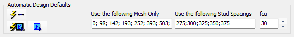
Automatic Design Defaults
Auto Design - 
Scan for Failures - 
Find next Failure (Worst Failure) - 
Use the following Mesh Only
This field allows you to specify a list of semicolon separated mesh sizes (mm²/m) that the software is permitted to use when performing an automatic design. The program will only select from this defined list to satisfy the transverse shear reinforcement requirements.
Use the following Stud Spacings
This field allows you to define a specific list of allowable longitudinal stud spacings that the software should consider during an automatic design. This is particularly useful, restricting the auto-design process to only use the spacings that you have provided in the list.
fcu
Change the characteristic compressive (cube) strength of the concrete (fcu), for auto-designs.
Old Manual Entry
The steel section size and grade are selected from the droplists. A minimum (H.min) and maximum (H.max) depth of section can be set so the droplist only includes sections within these parameters. This can be of benefit when there are floor depth restrictions applicable in the design criteria.
The area of transverse shear reinforcement is defined. You can either select a mesh area from the droplist or overtype it with your own area of reinforcement. This could be an area of bars placed over a metre length instead of mesh, eg, T16s at 300mm c/c (670mm2). There are 2 boxes for mesh - usually the top 'Mesh (mm2)' value is the area of global mesh which applies across the full floor and the 'Add. Mesh' which is an area of additional mesh to be located locally for the particular beam you are working on. The position of the mesh can be specified as either above the head of the studs or to be more than 10mm below the head. This can have an effect on the transverse reinforcement requirements.
In the shear connectors area there are 3 options available.
- Usually the number of studs per trough for a secondary beam is selected from the list. The capacity of the studs arrangement is then calculated as per the selected design code. For a primary beam the spacing of the studs can be set and whether these are single studs or a pair of studs. The 'As Welded Height' of the stud can be entered in mm. The British Standard asks for the stud height to be at least 35mm above the top of the troughs in the decking, whereas the EuroCode asks for this dimension to be 2 x dia of the stud, eg, 38mm for a 19mm stud.
- There is also an option for a raised rib pattern on the top flange surface which is usually found on Asymmetrical Slimfloor Beams (ASBs) in a slimfloor construction situation. In this case the raised rib pattern is transferring some of the load from the beam to the concrete in place of studs.
- The design can also be set so that the beam is considered as Non-Composite (NC). It is often the case that a short span edge beam is more efficient as a steel beam than a composite beam as not enough studs can be welded in place to transfer a share of the load from the beam into the concrete.
When sizing a beam you can manually move up or down the beam section sizes in the droplist until one passes or alter the studs and reinforcement area as necessary. Alternatively, the beams can be sized automatically. The Automatic Design Defaults can be used to size the beams, studs spacing and reinforcement area required. Automatic design also lets users to assign a '0' concrete grade to a composite design brief to force a non-composite design. A list of mesh sizes is already entered and can be added to or partially deleted to suit your design requirements. Stud spacings can be specified as well and the concrete grade for the slabs selected. To use the auto design click on the 'auto design'  option. The program will attempt to size the beam, studs and mesh for the moments and forces in the beam. Note that it doesn't take account of any openings when carrying out an automatic design.
When all the beams in a file have been designed, a 'scan for failures'  can be carried out. This will check all the briefs and highlight any that are failing. This is especially useful if a global parameter has been changed, eg, the concrete grade, to ensure all the beams still pass. Any failing briefs will be highlighted and you can move from failing brief to failing brief using the 'find next failure' option.