Analysing and Designing Cranked Beams Using Straight Segmented Members in MasterSeries
This guidance applies to cranked beams formed from straight segments (for example stepped beams, beams with vertical offsets, mansard or knee geometries) modelled in MasterFrame and designed using the Steel Design module.
Cranked beams cannot be designed as a single steel member in MasterSeries.
Each straight segment is:
Analysed as connected,
Designed independently.
Buckling lengths and LTB lengths must be reviewed and often manually adjusted.
Physical member (supermembers) do not apply to cranked geometry.
Overall deflection must be assessed from analysis results, not steel design outputs.
1. Fundamental Limitation: Cranked Beams Cannot Be a Single Design Member
In MasterSeries:
A cranked beam cannot be merged or concatenated into a single analytical or design member.
Members can only be merged into a physical member if they:
Are collinear (form a straight line), and
Have the same section size.
Because a cranked beam changes direction, each straight segment is always treated as a separate member for design, regardless of how it behaves structurally in reality.
This is a fundamental limitation of matrix-based structural analysis and applies across all MasterFrame Integrated Design modules.
2. Analysis vs Design: Important Distinction
Analysis
Frame analysis is always carried out on analytic members, i.e. members between nodes.
Cranked beams are analysed correctly as connected members with moment continuity at the crank node (provided no releases are applied).
The cranked structural analysis produces accurate analysis results
Design
Steel design checks are performed physical member by member.
There is no mechanism to design a cranked beam as one continuous steel element.
Each segment must be checked independently.
3. Modelling Requirements at the Crank
Members meeting at the crank should remain fully continuous unless a pinned joint is intended.
Any vertical segment forming part of the crank is treated as a beam or column element depending on the design brief applied, not automatically as part of the beam.
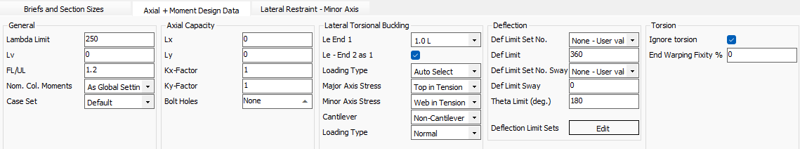
4. Buckling Lengths and Effective Lengths (Critical User Responsibility)
Because each segment is designed independently:
The buckling length defaults are based on the individual segment length, not the overall cranked beam length.
In many cases, this is not representative of the real structural behaviour.
Therefore, the user may need to manually adjust:
Effective length factors (k-factors),
Lx and Ly for axial buckling,
LTB lengths for lateral torsional buckling.
It must be noted that the axial and lateral torsional buckling design continues to be based on the assumption that the design member is straight. Where a cracked member is unrestrained though it's buckling plane length, this is obviously not the case.
5. Physical Members (supermembers): What They Can and Cannot Do
Physical members are a modelling and design convenience allowing multiple analytical member to be combined, assisting with geometric modelling, having common properties and be designed as one member.
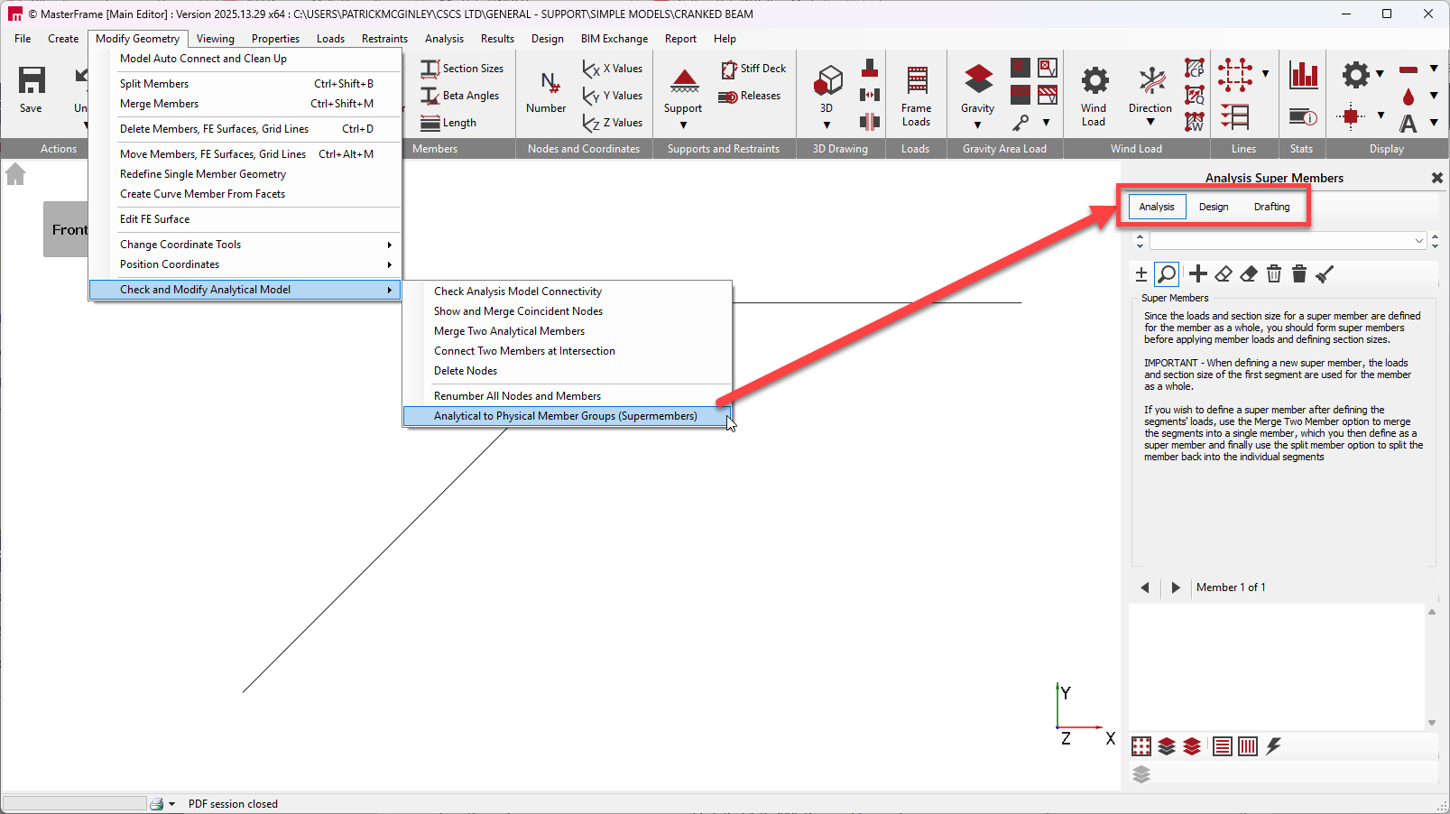
They:
Allow multiple straight, collinear members to be treated as one design entity.
Affect member length and buckling lengths only for straight members.
They cannot:
Be used for cranked beams.
Combine members with changes in direction.
Resolve buckling behaviour across a crank.
Attempting to use supermembers for cranked beams is not supported.
6. Moment Factors and Non-Eurocode Design
For Eurocode design, moment gradient and buckling factors are calculated internally.
There is no mechanism in MasterSeries to directly override:
mLT, mx, my, or myx,
or to manually force them to unity.
For non-Eurocode design:
The only practical control available is via effective lengths and LTB lengths.
Users should be aware that this may introduce conservatism.
7. Deflection Checks for Cranked Beams
Deflection is not assessed as a single beam in the steel design module.
Overall deflection must be reviewed in Graphical Analysis Results:
Check nodal deflections across the full cranked geometry.

Member diagrams will only show segment-by-segment behaviour.
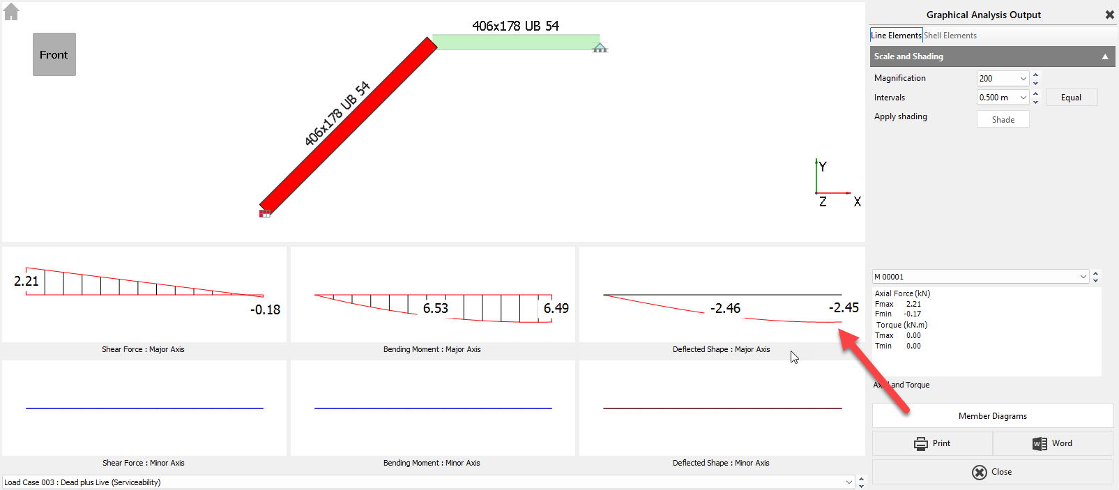
This is expected behaviour.
8. Vertical Segments Within a Cranked Beam
Short vertical segments are treated as individual members.
They are not automatically included in beam design checks.
Depending on the assigned design brief, they may be checked as:
Axial members,
Columns in simple construction,
Or beam-column elements.
The user must explicitly select the appropriate design brief and verify that the checks align with the intended behaviour.
Cranked Beam Connections in MasterSeries
MasterSeries does not currently include a dedicated cranked beam connection type. The closest applicable connection brief is the Beam-to-Beam Apex connection.
The Apex connection assumes a symmetrical geometry, meaning:
Both members are at the same pitch.
The connection is mirrored about the joint centreline.
This works well for portal frames where both rafters are at equal but opposite slopes. However, in a cranked beam arrangement where:
One member is horizontal, and
The other member is inclined,
the symmetry assumption is no longer valid, and a workaround is required.
Recommended Workaround (Matching Section Sizes)
Where both beam sections are the same size, the following method can be used:
Create a Beam-to-Beam Apex connection from the MasterFrame model for the joint in question.
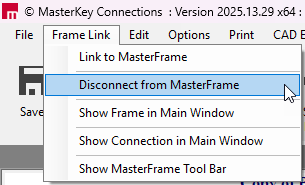
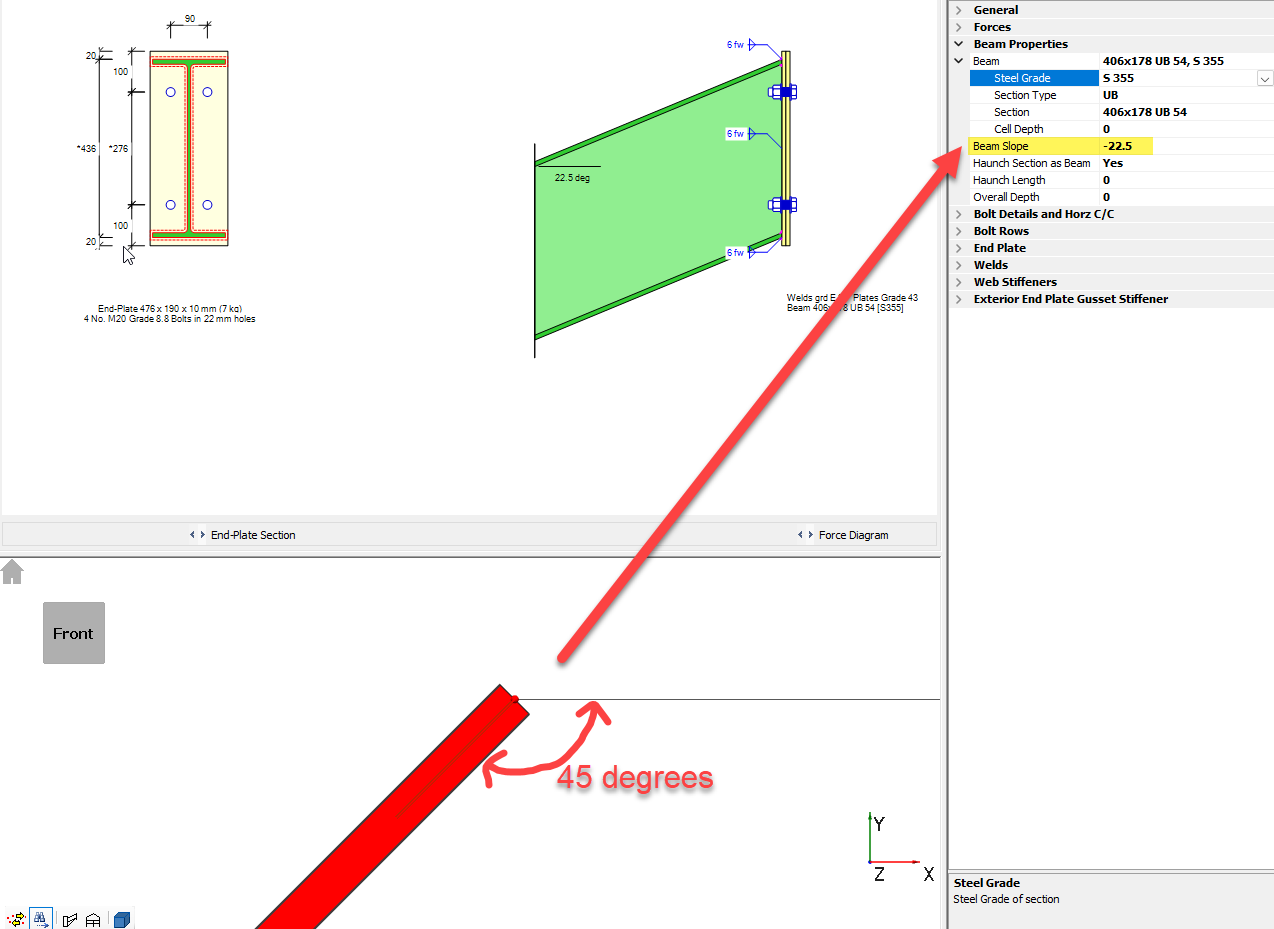
Once generated, you can unlink the connection from MasterFrame, which allows manual editing of geometry (including slope angle).
You can then set the slope angle to half of the actual cranked beam angle, ensuring the correct sign (+ or −) is used so the orientation aligns with the force direction.
Important Notes
Once unlinked, the connection is no longer associated with the MasterFrame model.
Any changes to the analysis model (member sizes, forces, geometry) will not automatically update the copied connection.
Forces must be checked and manually updated if the model changes.
For this reason, it is recommended that this workaround be used after the global model is finalised.
Key Limitation
This method relies on:
Matching beam section sizes.
Manual control of slope and forces.
Careful checking of orientation and moment direction.
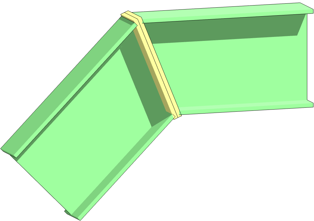
Sketch of 'Cranked Beam' type connection (image generated outside of MasterSeries)
Final Note on Responsibility
Reviewing whether the adjusted effective lengths, buckling assumptions, or restraint modelling accurately represent the real structure is a design decision. MasterSeries provides the tools to implement these assumptions but does not infer them automatically for cranked beams.