Gable Tab
Use the Gable tab to centralise all edits to the gable-end frame. Here you can override the main frame settings at each end by selecting the gable arrangement (portalised rafters/columns or post-and-beam), setting independent South and North gable member sizes (columns/rafters, with optional haunches), and adjusting connection intent (e.g., base fixity and simple vs moment joints).
Use it to keep the global model consistent while tailoring the end frames for buildability, openings, or façade requirements.
.png)
Gable Columns
Gable columns are primarily verified as vertical beams designed to span between the base and the rafter, typically resisting wind pressure and suction. The horizontal reaction forces exerted by these columns are typically transferred via the roof bracing and eaves down to the vertical bracing in the elevations and finally to the ground,.
Span No
Define the span number in which the gable column is situated.
X (m)
Enter the distance (X) from the Left Hand Column in the Span.
Global and In-bay Symmetry
You can append NN, YN, or NY to control the application of symmetry, even if the Global Symmetry and In-Bay Symmetry options are otherwise active.
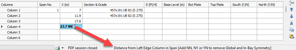
- NN
- No Global Symmetry
- No In-Bay Symmetry
- NY
- No Global Symmetry
- Yes In-Bay Symmetry
- YN
- Yes Global Symmetry
- No In-Bay Symmetry
Section & Grade
Specify the cross-section size and material grade for the column.
Beta Angle (β (PI/4))
This field controls the column's rotational orientation. By default, the major axis of the column is aligned perpendicular (at 90 degrees) to the main portal frame columns.
- 1 rotates the member by 90 degrees (π/2)
- 2 = 180 degrees
- 3 = 270 degrees
Base Level (m)
The base level of the gable column can be altered if required.
Bot Plate
For drafting purposes, specify the top and bottom plate thicknesses.
Top Plate (inc. Slotted Connection)
Specify the top plate thickness, used primarily for drafting purposes.
South (Y/N) / North (Y/N)
These options provide control over whether a set of gable columns is included (Y) or omitted (N) from the South or North gable frames.
Change Gable Frame Rafters and Columns from Defaults
To change the gable frame rafters and columns from these defaults, alter the values navigate to the 3d Bays Tab.
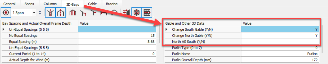
- Change South / North Gable (Y / N)
- Y - Will introduce a new option within the Columns tab
- N (default)
Change Columns at Gable End
Move to the Columns tab to change the gable main columns section. Select the S Gable button to move to the south gable, altering the section sizes in the different spans. Do the same for the north gable.

- North AS South (Y / N): You can opt to have the South and North gables with the same section sizes - enter 'Y' in the 'North as South' data cell. Entering 'N' means the gables can be different.
- Y (default): Same Section Sizes
- N: Different Section Sizes
Change Rafters at Gable Ends
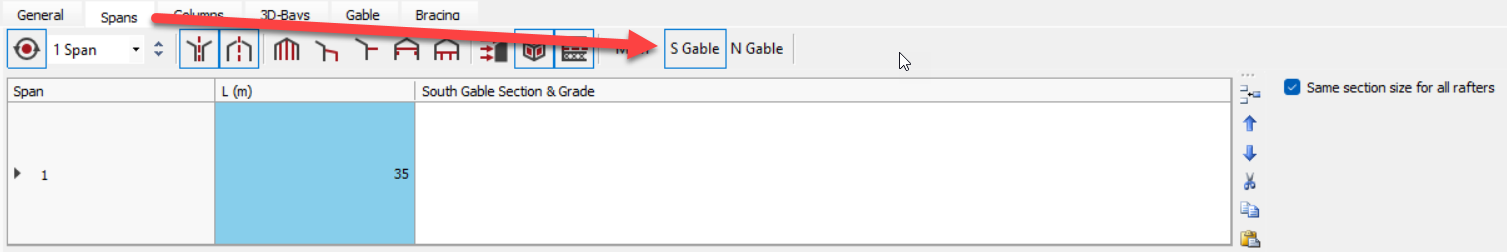
Move to the Spans tab to alter the rafter sections for both the south and north gables.
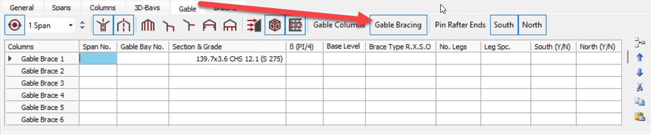
Pin Rafter Ends
If the gable end frame is to be designed as a beam and post rather than an end portal, the rafter ends can be set as pinned. 
Gable Bracing
Gable end bracing can be added by selecting the 'Gable Bracing' button on the 'Gable' tab.
.png)