Concrete Raft Slabs: Modelling Varying Ground Conditions
You can model different spring support conditions over multiple Finite Element (FE) surfaces by splitting them up in MasterFrame FE analysis.
This approach allows you to define distinct support properties, such as varying subgrade moduli, across different regions of what structurally functions as one large slab.
Here is an explanation of the process, including the role of dummy members, and how the assembly behaves as a single unit:
1. Modelling Different Spring Supports by Splitting Surfaces
To assign varying spring support conditions (like different Subgrade Modulus values) across a large area, you must define that area as multiple independent FE surfaces.
- FE Surface Definition: FE surfaces are defined by creating a closed boundary using linear elements. A line element can be shared between multiple FE surfaces to form a common boundary, which allows for subdivided slabs instead of one large region
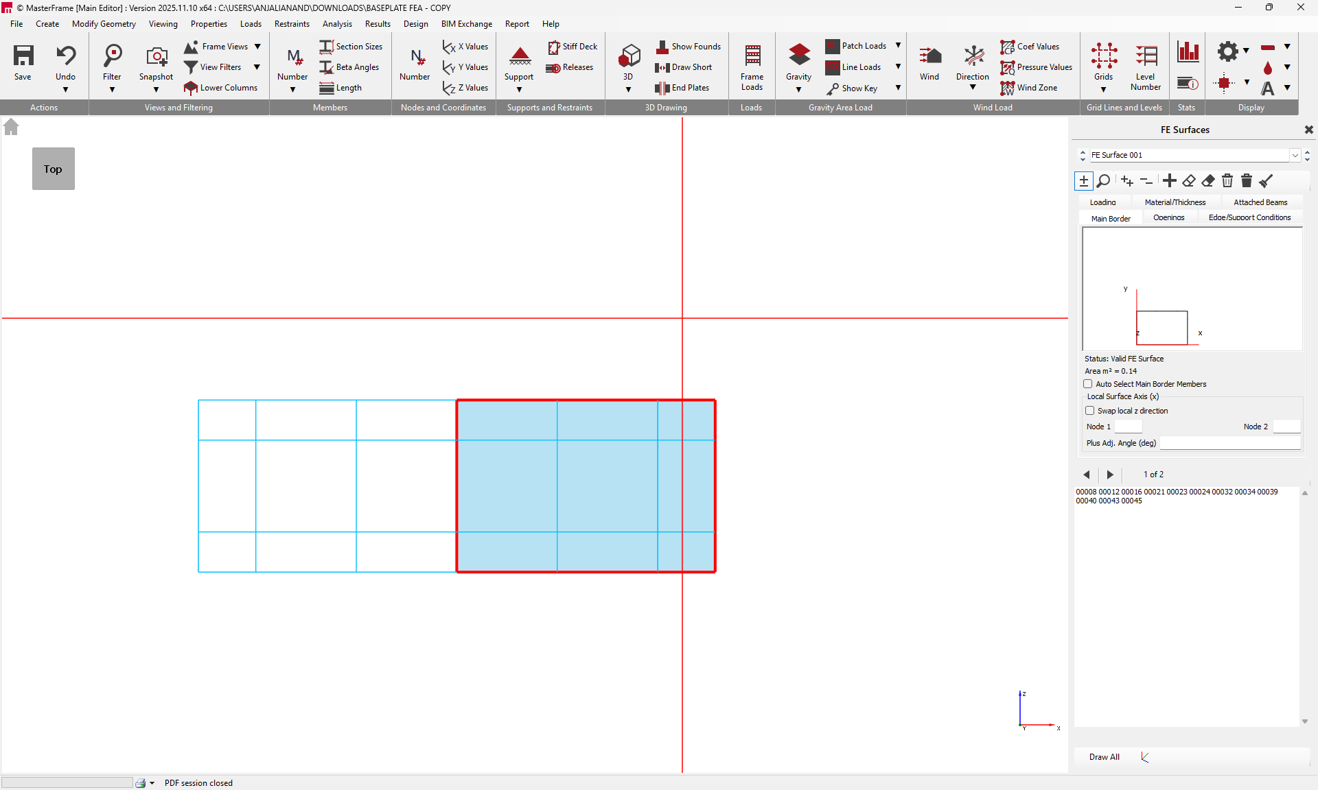
- Applying Spring Supports: The MasterFrame FE module allows for the definition of a Full Surface Area Vertical Spring Support for horizontal FE surfaces. This is defined by a spring stiffness value in kN/m² (often the subgrade modulus, e.g., 10,000 kN/m²).
- Varying Conditions: Because the spring support is applied to the entire area of the defined FE surface, creating multiple FE surfaces allows you to assign a unique spring stiffness value to each surface, thus modelling the variation in soil conditions. These spring supports can also be set as compression-only, which triggers an iterative non-linear analysis to remove tension zones.
2. Use of 'Add Dummy Member'
The line elements used to form the boundaries between your split FE surfaces often relate to the concept of dummy members:
- Boundary Definition: The boundary members used to define the perimeter of an FE surface or an opening are created using standard MasterFrame line elements. You can right click in the model space and 'Add Dummy Member' to quickly add dummy members within the FE Surface interface.
- Automatic Classification: If a boundary member is not explicitly designated as an attached beam within the FE menus, the software automatically disregards its section properties and classifies it as a Dummy FE Member. Since you are splitting the surface purely for support modelling, the internal boundaries between the newly created FE surfaces would typically be composed of such members, having no structural properties themselves.
- Dummy Members for Meshing/Subdivision: While dummy members are ignored in the frame analysis, they are critical for geometry definition and meshing. For a very large FE surface with many geometric constraints, it may be necessary to introduce additional dummy members internally to the surface to divide it into smaller regions, assisting the mesh generation algorithm. In this case, splitting the surface using shared boundary members achieves a similar effect, defining the geometric boundaries necessary for the different spring properties.

3. Meshing and Structural Behaviour
Although the system uses multiple geometrical surfaces, the structure will behave as one large continuous surface, provided connectivity is maintained:
- Continuous Structural Behaviour: The division of a slab into multiple FE surfaces does not affect how the element behaves structurally. For analyses like deflection and cracking, the software automatically includes all connected FE surfaces, treating them together, unless they have a full edge release condition defined at their common boundary or are physically disconnected.
- Mesh Generation: The FE mesh is generated automatically using a built-in algorithm that subdivides the plate into finite elements.
- Spring Stiffness Distribution: The spring stiffness defined for each FE surface is converted into a linear elastic vertical spring on each node of that surface's mesh. The software automatically uses the mesh size to adjust the individual spring stiffnesses on each node, and recalculates the stiffnesses when the mesh is regenerated to account for geometry changes.
- Mesh Compatibility: Where two FE surfaces share a common boundary (a line element), the mesh generation must ensure compatibility between the finite element edges and nodes across that boundary so that they act together. If no releases are applied along the shared boundary, forces and moments transfer continuously between the adjacent surfaces, making them act as a single continuous plate supported by the defined springs in each region.
In essence, by splitting the surface with shared boundaries (composed of dummy members or non-attached line elements), you are creating geometric partitions that allow for localized spring definitions, while the continuous nature of the FE mesh ensures that the physical slab behaves as a single large structural entity.