Linear Shear Checks (Strip Zones)
MasterSeries provides graphical contour plots to help users quickly identify areas of an FE slab that may require more detailed shear assessment. In particular, the Shear Unity Ratio Contour highlights regions where the basic unreinforced shear capacity of the slab is exceeded, acting as an initial screening tool.


Shear Check Settings
Slab Image – Shear Unity Ratio Contour Plot
Specifically:
Punching shear reinforcement is not included within the punching shear perimeter (typically at u₁ or 2d), and support face enhancement effects are also excluded.
Linear beam shear reinforcement is not considered. For transfer slabs, the contour is therefore often governed by the basic linear shear capacity, which is intentionally more onerous and conservative than the punching shear assessment close to the column.
The Shear Unity Ratio Contour outputs are intended to flag potentially critical regions and prompt the engineer to carry out the appropriate detailed punching or linear shear checks, rather than being used directly for design acceptance.
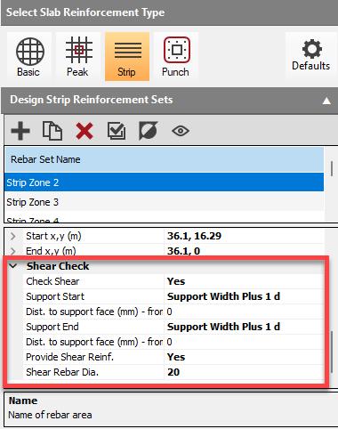
Shear Check Inputs
Check Shear
Checks the capacity of the slab against the design shear force (VEd,linear) occurring along the strip length.
- Yes: activate the linear shear check along the specified strip line.
- No: the strip will only be checked for flexural capacity (moment design).
Support Start
- No Support: Shear Value taken at the node
- Support Width: Shear Value taken from the face of the support
- Support Width plus 1d: This is generally the recommended option for performing linear beam shear checks, as the critical shear section is typically located at a distance d (effective depth) from the face of the support.
- Support Width plus 2d: This option checks the shear at a distance 2d from the support face, which is typically used for defining the basic control perimeter (u1) in traditional punching shear checks
Dist. to Support Face from Start / End
- Value in mm (e.g., 200 mm)
Provide Shear Reinforcement?
Direct the software whether to provide vertical shear reinforcement (shear links) if the capacity of the unreinforced slab (VRd,c) is exceeded at the critical section.
- Yes to enable the software to apply shear reinforcement.
- No indicates that no shear reinforcement is to be provided, and a failure will be reported if capacity is insufficient.
Shear Rebar Diameter (if required)
Input the diameter (in mm) of the shear links (vertical reinforcement) to be used if reinforcement is required. The software will output the required longitudinal and transverse spacing based on the selected diameter.
- Value in mm (e.g., 10, 12, 16)
The maximum spacing for shear links in the direct transfer zone is generally recommended to be limited to 0.75d longitudinally and transversely.
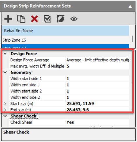
Design Force Average (over control perimeter)
Select the method for the design force averaging.
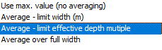
Design force averaging is always perpendicular to the direction of the rebar. The appropriate averaging method depends on the type of shear assessment being conducted:
Max Average Width Effective Depth Multiple
Specify the maximum width as a multiple of the effective depth over which the design force will be averaged. This helps prevent over averaging for wider rebar strips.
When determining the maximum permissible averaging length (Lavg) for shear assessments in transfer slabs, the effective depth (d or D) is used to define the primary width limit.
- Use Max Value (no averaging)
- Average – limit width (m): Takes the averaging width over a specified length of the control perimeter
- Average – limit effective depth multiple: Takes the averaging width over a specified depth multiple of the control perimeter
- Average over full width: Averages the force over the full control perimeter
When conducting linear shear checks in the Strip Reinforcement module, the design shear force is derived from Finite Element Analysis (FEA) results. The maximum shear value is calculated by applying design force averaging across the width of the strip.
Geometry (Notional ‘beam zone’ width)
For internal columns, the IStructE guidance states that the notional beam zone (width) should extend 2d to either side of the centreline between the planted and supporting columns, giving an overall beam zone width of 4d.
- Width Start Side 1: 2d effective depth
- Width End Side 1: 2d effective depth
- Width Start Side 2: 2d effective depth
- Width End Side 2: 2d effective depth
- Start x,y: Input (or draw) start co-ordinates
- End x,y: Input (or draw) end co-ordinates
The ability to perform linear shear checks within the strip design facilitates compliance with detailed guidance for elements like transfer slabs, where reliance solely on the standard EC2 punching shear method (which assumes predominantly uniform loading and uses the beta-factor) is considered potentially unsafe due to the concentrated nature of transfer loads.