Stiff Decks in MasterFrame: Managing Compatibility with your Steel Connection Designs
See 📄 Add Stiff Deck, Semi Rigid
The Stiff Deck feature is designed to model the diaphragm action of a floor slab or plate, facilitating the distribution of lateral loading back to the bracing frames, cores, or moment-resisting frames that constitute the structure's lateral stability system. It is applicable to horizontal and sloped surfaces but is not permitted on vertical surfaces (slopes greater than 80∘ from horizontal).
Internal Stiff-Deck membrane forces are not currently displayed graphically in MasterFrame, the user cannot directly see these in-plane stresses or tensile forces.
.png)
Mechanism and Stiffness
The underlying mechanism of the semi-rigid Stiff Deck is crucial for understanding its impact:
- Stiffness Addition: The stiff deck generates a coarse finite element mesh internally, using triangular plane stress elements between existing analytical nodes.
.png)
- Inputs: The stiffness is based on user-defined inputs for the Stiff-deck Thickness (mm) and the Young's Modulus (E kN/mm2). When determining the equivalent thickness for composite floors, it is generally advisable to use the thickness of the concrete above the ribs, as the diaphragm bends in its own plane.
- Degree of Freedom: This method only adds extra stiffness to the in-plane translational degrees of freedom (e.g., global X and Z directions for a flat floor). It does not add out-of-plane bending stiffness.
- Vertical Loading/Mass: The Stiff Deck surface itself cannot be loaded vertically. Crucially, the mass of the deck is not accounted for by this feature and must be manually added to the model using area loading or member loading. Similarly, the vertical deflection and vertical stiffness of the bounding members remain unaffected.
.png)

Stiff Deck 'Hidden' Forces
While a stiff deck can improve overall stability, it also redistributes forces in ways that are not always obvious:
The deck connects the nodes of all attached members, so it automatically develops in-plane tensile or compressive forces as the structure deforms.
In a truss, for example, the stiff deck on the bottom chord can act as a hidden “plan tie,” transferring axial tension from one end of the truss to the other.
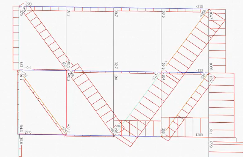
Redistribution of Axial Member Stresses without Stiff-Deck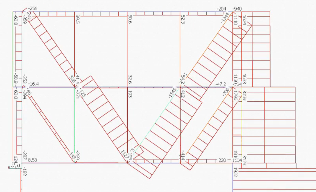
Redistribution of Axial Member Stresses with Stiff-DeckThis reduces the visible axial stress in the bottom chord members themselves as the deck is doing part of the work behind the scenes.
- Stiff-Deck membrane forces are not currently displayed graphically in MasterFrame, the user cannot directly see these in-plane stresses or tensile forces.
Workaround to Makes Stiff Deck Forces 'Reappear'
You can use dummy members to pull the stiff back away from the corners, this will allow the forces to be brought back into the steel members.
See example below of 2 identical frames, the frame on the left shows the stiff deck 'pulled away' from the corners of the frame.

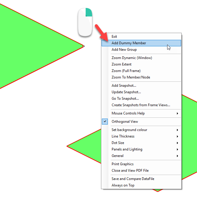
You can 'Add Dummy Member' by right clicking within the graphics pane, and use this to redefine the boundary of the stiff deck.
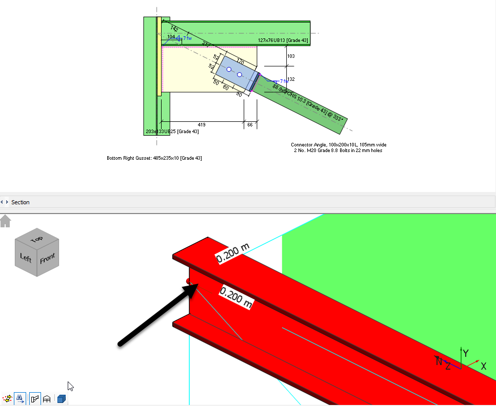
Steel Bracing Connections Design: The stiff deck 'opening' may need to be a minimum of 0.2m to allow the software to detect the beam for the joint arrangement for braced bays for the Integrated Connections Design checks.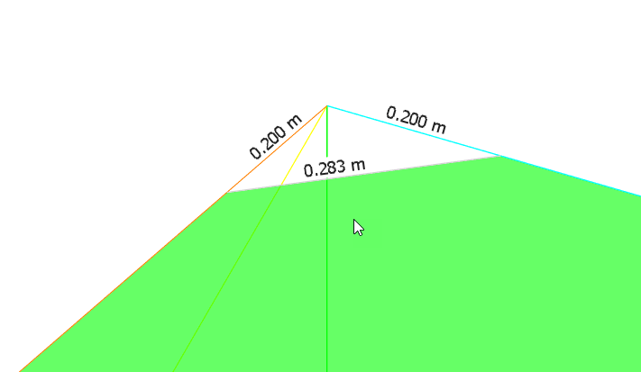

Axial forces now 'reappear' at the member ends

Steel Connections Module Integration
Due to the new 0.2m long member element, it is important to click on the correct end of the correct member to be able to detect the joint configuration within the Steel Connections Design module, to obtain the correct loads - this may require you to zoom in on the joint.
Upper / Lower Boundary Checks
You may want to run the analysis with and without the stiff deck to see its influence on axial and shear forces.
A stiff deck is a powerful modelling tool when used intentionally, it ties your structure together and provides realistic diaphragm stiffness.
But remember: it can also carry these 'hidden' axial forces. Always confirm that the deck’s behaviour matches your design intent.
See Also