Torsion Design Inputs
The Torsion inputs define how MasterSeries checks members subject to torsional loading. These options let you decide whether torsion should be included in the design, and how end restraints are modelled.
When a load is applied eccentrically to a beam or frame, the global frame analysis in MasterFrame considers only the St Venant (uniform) torsional stiffness of the members.
It does not include the effects of warping torsion, as that would require a higher-order (second-order) analysis to capture warping restraint and the associated stiffness accurately.
However, during the Steel Design stage, the software does account for warping stiffness, in accordance with the guidance in SCI P385 – Design of Steel Beams in Torsion.
As a result, the torsional rotations and stresses reported in the Steel Design module are more accurate representations of the member’s real torsional behaviour than those obtained directly from the initial frame analysis.
In short:
Frame analysis → only basic (St Venant) torsion.
Steel design → includes warping torsion (per SCI P385).
Therefore, torsional results in the design output are more realistic.
SCI publication P385 provides a rigorous theoretical and practical basis that aligns with Eurocode 3 §6.2.7 and related clauses.

Ignore Torsion:
Skip torsion checks for the member
- Toggles torsion checks on or off for the member.
If selected, torsional effects are ignored in the design brief.
End Warping Fixity %:
Define how much restraint against warping each end provides
- Defines the degree of restraint to warping at each member end.
Value is given as a percentage:
0% = free to warp (no torsional fixity).

100% = fully restrained against warping.

Member Torsion Property Diagram:
View torsion properties for QA
A visual diagram of torsional properties can be displayed via the Options menu → Draw Member Torsion Property Diagram.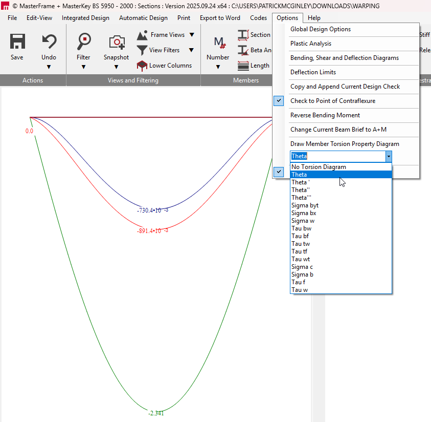
This helps visualise how torsional stiffness and warping are being modelled for the member to help confirm that torsional properties and restraints are being applied as you intend.
Global Option – Check Torsion:
Switch torsion design on/off for the entire model
- To turn torsion design on/off for the entire model, go to:
Options menu → Global Design Options → Check Torsion.