Axial Capacity Inputs
The Axial Capacity inputs define how MasterSeries calculates a member’s resistance to axial compression and combined axial + bending. These settings allow you to model the effects of real restraint conditions, torsional stability, and connection detailing (e.g. bolt holes).

Restraint Lengths Lx / Ly:
Distance between axis restraints
- Lx = Distance between restraints to the major axis (strong axis).
Ly = Distance between restraints to the minor axis (weak axis).
If set to 0, the software assumes the full member length is unrestrained.
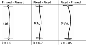
Kx / Ky Factors:
Effective length factors (end fixity)
- Kx-factor = Effective length coefficient for the major axis.
Ky-factor = Effective length coefficient for the minor axis.
Adjusts the effective buckling length to account for end fixity conditions.
- Pinned–pinned ends → K = 1.0
- Fixed–fixed ends → K ≈ 0.7
- Fixed–pinned ends → K ≈ 0.8–1.0
- Cantilever → K = 2.0
Choose factors that reflect how your member is connected in the frame model.
Kt Factor (Eurocode) - Axial Torsional Buckling
Torsional buckling factor (only if torsion check is active)
- Kt-factor = Effective length factor for torsional or flexural–torsional buckling.
Only active if the Check for Torsion option is switched on.
If set to 0, the software uses the actual member (or segment) length.
Bolt Holes
Adjusts net area to reflect connection detailing
Bolt holes reduce the net area of the section and therefore its axial capacity. Inputs are provided to model their effect directly in the design checks.
Flange Holes (F-Holes, F-Diameter): Enter the number and size of holes in the flange.
Web Holes (W-Holes, W-Diameter): Enter the number and size of holes in the web.
For angles connected by a single leg, additional inputs are available to refine the effective net area:
Bolts in Row No. = Number of bolts in the connected leg.
Bolt Pitch (P1) = Centre-to-centre spacing of bolts.
Bolt Edge Distance = Distance from edge of section to nearest bolt centre.