
Importing a Snappable CAD Layer from a DWG/DXF
To import a CAD drawing as a snappable 2D underlay within MasterFrame, follow these concise steps:
Preparation:
- For optimal performance, strip the CAD file back to only the necessary layers and move them close to the 0,0 origin. This reduces the amount of data MasterSeries needs to process.
Importing the CAD Layer:
- Open MasterFrame and create a new file or open an existing one.
- Navigate to the 'Viewing' menu and select 'Cad Layer'.
- Click the '+' icon to generate a new MasterFrame CAD Layer
- In the 'Cad File Path, click the '...' button in the cell to choose the path to your CAD drawing file.
- Select which CAD layers you wish to see and snap to. You can turn off unnecessary layers (e.g., fixtures, doors, windows). You can also specify which layers you are interested in snapping to (e.g., centre lines, grid lines). Right clicking on the header of the 'Display' and 'Snappable' column to access quick options to select/deselect all layers. It is advisable to limit these to only what is necessary. Click 'Next'.
- Select the portion of the drawing you wish use by holding down the 'Shift' key and click and dragging to select the area on the drawing. This will fill in the 'Top Left' and 'Bottom Right ' CAD space coordinates.
- Set your anchor point on the CAD drawing by holding down the 'Ctrl' key and double-clicking at a point to define the desired location in MasterFrame. This complete in the 'Anchor Point' CAD space co-ordinates. The anchor point then then be aligned with a MasterFrame 3D point. Click 'Finish'. The 'Anchor Point' is now reflected in the 'CAD Reference Point'
- In the MasterFrame CAD Layer settings specify the
- units in which the drawing was created
- the principal plane (e.g., XY plane) that the CAD layer is associated with. The CAD layer will only be visible when your view is precisely oriented to this plane.
- The rotation angle of the CAD layer in this plane.
- The MasterFrame Reference Point X,Y and Z coordinates which align with the previously selected CAD space 'CAD Reference Point'. You can use the 'Pick' anchor point button to graphically select this point in the MasterFrame model.
- You can also adjust the 'CAD Reference Point' if required
Using the CAD Layer:
- Once imported, the CAD layer provides snappable entities that assist in drawing new structural elements, loads, or gridlines. You can snap to lines, midpoints, third points, and utilise tracking points/lines. This is particularly useful for applying loads like line loads and patch loads by tracing over elements such as block walls.
- To snap to the CAD layer you must
- Be in drawing mode that supports snapping, e.g. create member, add column, draw are line/patch/point loads, draw FE Surface Line/patch/Point loads, draw Slab Design rebar etc.
- Ensure you are in a view the is in the principal plane of your CAD layer, e.g. plan view.
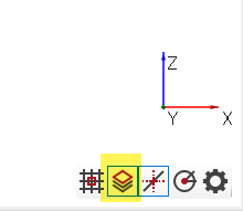
- Turn on the CAD layer snap option from the snap tool bar at the bottom right of the graphics window. If you cannot see this tool bar you are likely not in a drawing more that uses snapping facilities.
- MasterFrame allows for multiple CAD layers to be set up, potentially representing different levels or sections of a building.
- The CAD Layer will only provide snap point on it's plane. For example, if the CAD Layer is on the XZ (plan View) plane and anchored to a Y coordinate in 'CAD Reference Point' above, the the snap points will only be at that Y coordinate. You can edit the Y value of the MasterFrame 'CAD Reference Point' if you which move this CAD layer to a different level Y value.
Notes
Whilst all CAD object types can be shown in the CAD layer, only the following object types in the CAD drawing are translated to MasterFrame Snap points
- Line
- 2D Polyline
- 3D Polyline
- Light Weight Polyline
Blocks and nested blocks in drawing should be exploded.
Splines, Arc, Circles will not be snappable in the CAD Layer