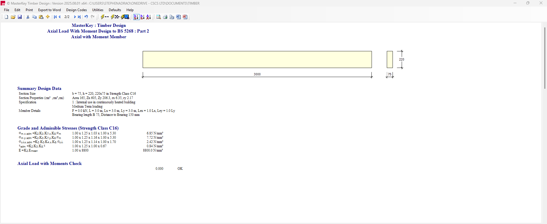
Standalone Timber Rafter Design
The following steps outline the basic process for timber rafter design using the standalone version of MasterKey Timber Design, focusing on the necessary input areas within the software interface.
Accessing the Standalone Module
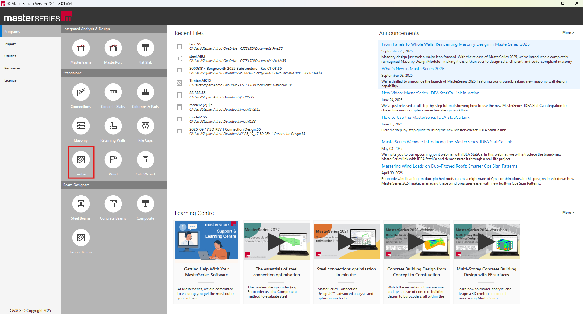
To access the timber module, launch the MasterSeries suite and select the MasterKey Timber Design application, which operates as a standalone piece of software independent of the MasterFrame modelling environment.
Set Design Code and Environment
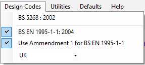
Upon launching the module, the first action is to confirm the required design standard. Navigate to the Design Codes menu and select the appropriate standard (e.g., BS EN 1995-1-1: 2004) and any relevant National Annex.
Define Materials and Section Properties
The primary specifications are controlled via the Material and Specifications tab:

Section Definition: Select the section shape (Rectangular, Square, or Round) and the Section Type (Sawn, Planed, or Regularized Section). Input the exact Section Size (Breadth and Depth).
Grade Selection: Choose the appropriate Strength Grade (e.g., C24). User-defined grades can be added via the Utilities Menu if needed.
Flitched Beams: If a flitch beam is required, enable the option. You must define the Beam Alignment (Vertical or Horizontal), the number of Timber Members and Plate Members, the Plate Grade, Plate Size, and Bolt Diameter.
Specify Design and Modification Factors
In the Specification and Modification Factors area, critical parameters governing capacity are set:

Environmental Factors: Define the Load Duration (e.g., Long Term, Medium Term) and the Service Class (e.g., SC1).
Bearing Constraints: Specify the bearing support conditions for the Major and Minor axes using the Major and Minor factors, which represent rotational and translational constraints.
Input Member Geometry and Serviceability
The Axial with Moment tab manages geometrical details and deflection checks:

Dimensions: Input the physical dimensions, including the Bearing Lengths and Distance to Bearing for both X-X and Y-Y axes (in millimeters).
Effective Lengths: The effective lengths used for stability checks can be defined using the factors or by inputting Member Length Lx and Ly . The design also requires setting the Beam Buckling condition (e.g., "Fully restrained on compression side") and the relevant factor.
Serviceability Checks: If required for deflection and vibration checks (e.g., for floor joists or rafters supporting specific deck types), input the Deflection Limit, Young’s Modulus of Decking, Deck Thickness, Floor Width, Beam Spacing, and Mass of Decking.
Design and Review
Once all inputs are complete, the design check can be initiated:
Design Check: Use the Auto Design icon ( ) to automatically find a passing section, or manually adjust the section size in the Materials and Specifications tab.
Results: The resulting analysis checks are immediately displayed in the Timber Design Calculations area, showing the Unity Ratios for compression, axial load with moment, shear, bearing, and deflection. The design is acceptable if all unity ratios are 1.0 or below, resulting in an 'OK' verdict.