Modelling Partial Base Fixity with Equivalent Rotational Springs (for Split Columns)
It’s common to split portal columns near the base (e.g., to model cladding extents, brace nodes, offsets). If you then apply, say, 20% fixity at the base to the short bottom segment, the effective rotational spring becomes much stiffer than intended.
When a column is split into multiple analytical members, MasterFrame’s built-in partial fixity uses the split member length, not the full physical column. This can under-stiffen the base.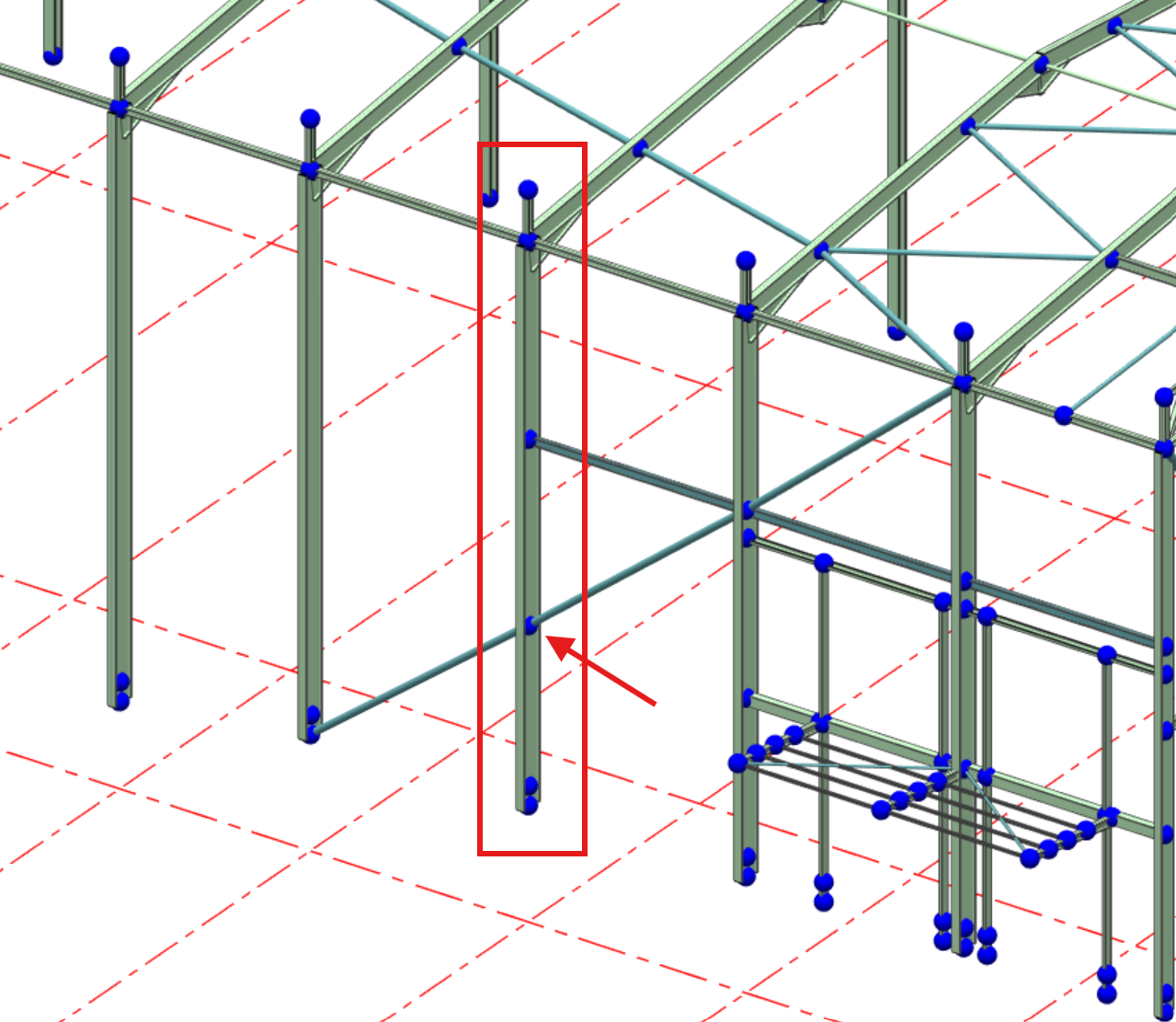
Workaround
Where a base needs partial fixity for serviceability checks, add an equivalent rotational spring at the base using the full physical column length. Activate this spring only in your SLS load case (e.g. N2).
Rotational spring stiffness for a % fixity
For a column of flexural rigidity EI and full physical length L, the fixed-end rotational stiffness is 4EI/L.
For a target partial fixity fraction f (e.g. 20% → f=0.2):
kθ=f×4EIL
E: Young’s modulus of the column material
I: Second moment of area about the base bending axis (use the major/minor axis appropriate for the frame sway direction)
L: Full column length from base to the top restraint level (ignore analytical splits)
kθ: Rotational spring stiffness to apply at the base node (units of moment/radian)
How to set it up in MasterFrame
Keep the base pinned
At the base support, set rotations free (pinned) in the relevant bending axis (e.g. about local Z or Y as appropriate).
Add a rotational spring at the base
Go to Restraints / Nodal Static Supports → Springs.
Add a Moment Nodal Force (Spr _) at the base node about the correct local axis with stiffness kθ=f⋅4EI/L computed using the full column length.
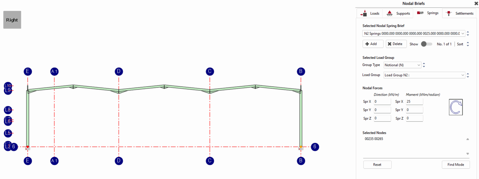
Make it case-specific (SLS only)
Assign the spring to your serviceability load case (e.g. N2).
Ensure the spring is inactive for ULS combinations if you only want partial fixity considered at SLS. (Use case activation/combination participation controls.)
NOTE: You should not also set “partial fixity” on the member. Avoid double-counting. Leave member end releases as pinned; the spring alone provides the rotational restraint.
If the base has partial fixity in both axes, calculate and apply a spring for each relevant axis using that axis’s I.
Why this works
The spring uses L for the physical column, so it’s independent of analytical splits used for cladding, braces, nodal inserts, etc.
You can scope it to SLS (e.g. N2) so ULS design remains on conservative pin/fix assumptions as you prefer.
It avoids the common pitfall where member-based partial fixity is tied to a short split length, skewing stiffness and deflections.