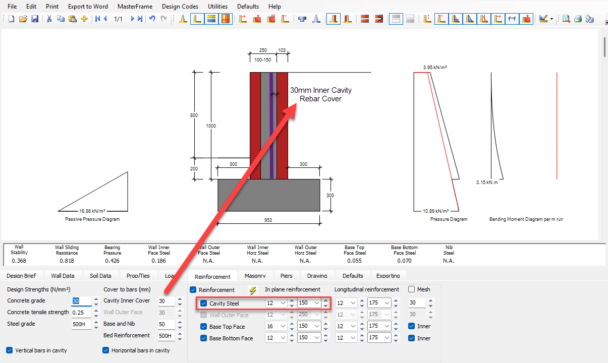
Reinforcement Tab
The concrete and steel strengths, bar covers and reinforcement sizes and spacings are defined for the RC wall and base under this tab.
.png)
Concrete and Steel Strengths
Concrete grade
- For BS design, the concrete tensile strength defaults to 0.25 N/mm², and you may edit this value if required.
- For EC design, the concrete tensile strength is calculated automatically by the program.
Reinforcement steel
Bar Covers
- Wall inner face
- Wall outer face
- Base and Nib (if present)
Reinforcement Layout
In the reinforcement area the bar sizes and spacings are set for the 4 faces of the wall and base, for both the in-plane and longitudinal reinforcement.
In-plane reinforcement (main bending steel)
This is the vertical reinforcement that resists bending of the wall stem.
Longitudinal reinforcement (distribution steel)
This is the distribution reinforcement provided along the length of the wall.
You can decide whether the longitudinal reinforcement is on the inner or outer side of the in-plane main bars.
Automatic Reinforcement Design
The yellow lightning flash  button will produce an automatic design for the reinforcement. This option sizes and spaces reinforcement based on the current geometry, loads, and design code settings.
Mesh Bar Sizes Option
Tick Mesh to add intermediate bar diameters commonly used in welded mesh reinforcement to the bar size drop-down list, for example:
5 mm
7 mm
9 mm
Cavity-Filled Masonry Walls
- Vertical bars in cavity
- Horizontal bars in cavity
Reinforced Hollow Block Retaining Walls
- Hollow blocks act primarily as permanent formwork
- The wall is infilled with concrete
- Vertical bars provide main reinforcement
- Horizontal reinforcement provides distribution steel