Loads Tab
The Loads tab is used to add loads acting on the wall in addition to soil pressure. These may include vertical line loads, surcharge loads on the backfill, and horizontal loads applied above soil level.
- Loads from upper walls or floors bearing onto a basement retaining wall
- Localised loads on the wall or base
- Traffic barrier impact loads
- Wind loads acting on an upstand wall
The loads entered here are combined with the soil pressures in the wall stability and structural design checks.
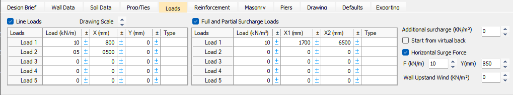
Line Loads
- On top of the wall
- To the back of the wall
- To the front of the wall
Load position reference
Load positions are defined using X and Y coordinates in mm.
X is measured from the back face of the wall (the face in contact with the retained soil)
Positive X values place the load to the right of this face (on or within the retained soil)
Negative X values place the load to the left of this face (on the wall top or in front of the wall)
- The Y dimension is measured downward from the top of the wall:
A positive Y value places the load below the top of the wall
Vertical loads placed in front of the wall are commonly positioned on the top of the base by entering a suitable Y dimension.
.png)
The loads and dimensions in the table above will place loads on the inner and outer leafs of the wall at the top, see diagram below.
.png)
The table below gives a 12 kN load placed on the base, at a Y dimension of 2.3m. The 16 kN load placed at -0.55m from the back of the wall not only produces a vertical load but also a moment. It is assumed to be a point load sitting on a bracket or beam protruding from the front of the wall.
.png)
.png)
Full and Partial Surcharge Loads
Surcharge loads can be applied over the retained soil behind the wall. Surcharges are entered in kN/m² (based on a wall length of 1 m into the screen depth).
For each surcharge, enter:
The surcharge value
The start position
The finish position
The start and finish positions are measured in mm from the back face of the wall.
- Full surcharges acting across the full retained soil area
- Partial surcharges acting only over a selected zone behind the wall
.png)
The dead load in the table above of 3.65 kN/m2 starts at 1.2m behind the wall and finishes at 2.5m. Note the shape of the pressure diagram below where a kink occurs part way down the wall. This represents the change in horizontal pressure applied to the wall due to the positioning of the surcharge load.
Effect on pressure diagram
A partial surcharge changes the horizontal pressure distribution on the wall. This is shown in the pressure diagram, where a kink appears at the depth where the surcharge influence changes.
This visual check helps confirm that the surcharge has been applied over the intended area.
.png)
Horizontal Loads
The Loads tab also allows you to define horizontal loading effects in addition to soil pressure.
Additional surcharge influence zone
An additional surcharge may be entered as a load applied from the back of the wall to a defined horizontal distance, beyond which it is assumed to have no influence on the wall pressure.
Horizontal surge force above soil level
- Vehicle barrier impact
- Other local horizontal forces acting above ground level
- A horizontal force
- An additional moment on the wall
Wind load on wall upstand
Where the wall includes an upstand above the back soil level (defined on the Wall Data tab), a wind load can be applied to the upstand.
- Car park upstand walls
- Garden walls
- Fences or parapet type walls
- A horizontal force
- An additional moment
.png)
.png)