Zero Stiffness Terms in Finite Elements Bounded by Nodes
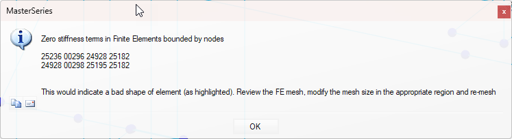
When analysing a finite element (FE) surface in MasterSeries, the message:
“Zero Stiffness in Finite Elements bounded by nodes”
indicates that the analysis has identified a structural instability due to a bad mesh shape, e.g. where a quad element has gone triangular or concave in shape. The result is an unsolvable system of equations.
More information on generating your mesh can be found in 📄 FE Meshing.
1. Meshing Errors and Poor Mesh Geometry
The accuracy of FE analysis relies on good mesh quality.
If the meshing algorithm produces badly shaped elements (e.g. nearly triangular or concave), stiffness terms become invalid.

Common triggers:
Openings too close to slab edges or to each other.

Narrow wall strips or small gaps forcing small/distorted elements.
Too many isolated internal nodes for the mesher to conform to.
Overuse of stiff regions (especially wall stiff regions) can also force very small elements.
Columns or strips too close to edges

a. Overuse of stiff regions
Stiff regions around walls, often lead the auto-mesher to struggle and generate poorly shaped elements, leading to the zero-stiffness node errors you’re seeing.
In most cases, applying stiff regions to column heads only is suffice. Results along the wall are generally less critical than at column heads and may create excessive mesh constraints and small, distorted elements.
- Try only disabling the stiff regions at wall locations. Instead, rely on the columns only, and use local mesh refinement around the ends of the shear walls.
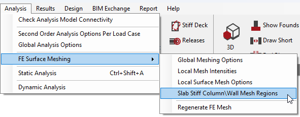
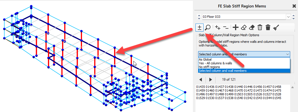
- Go to the Analysis Menu -> FE Surface Meshing -> Slab Stiff Column / Wall Mesh Regions.
- Use Selected column and wall members and choose the columns only.
- You can also amend the As Global option settings Under Analysis Menu -> FE Surface Meshing -> Global Meshing Options
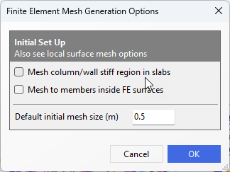
- For locations of stiff regions, you can try reducing the mesh size down to allow for more continuous meshing.
- Try only disabling the stiff regions at wall locations. Instead, rely on the columns only, and use local mesh refinement around the ends of the shear walls.
b. Rogue nodes & members
All nodes are structural and any nodes inside or on the boundary of the FE surface need to be meshed.
look out for the following that can create complex an unnecessary meshing constraints
nodes that are too close together relative to the global mesh size
nodes that where created for drafting or load placement only are not required for meshing and can be removed
Member arrangements that create small or complex shapes
Internal node close to a boundary where there is no perpendicular boundary node
2. Mesh Settings and Transition Rules
Global mesh size set too large relative to model detail can produce distorted elements.
Local mesh refinements applied too aggressively create abrupt transitions.
Rule of thumb for radius of influence:

where b = global mesh size, a = local mesh size.
If this rule is not respected, elements may be forced into poor shapes, leading to zero stiffness terms.
3. Recommended Solutions
Check Geometry
Remove redundant or drafting-only nodes inside FE surfaces.
Simplify wall layouts and widen narrow strips around openings.
Where poor meshing quality occurs at an internal node close to a boundary, place an additional control node on the boundary. This can often be done most conveniently by adding a member starting at the internal node then snapping perpendicular to boundary element for the second node.
Improve Mesh Quality
Reduce global mesh size where detail is high.
Apply local mesh refinement with a sufficient radius of influence to ensure smooth transitions.
Visually inspect the mesh for distorted elements.
Manage Stiff Regions Selectively
Do not globally enable “mesh to all stiff regions.”
Activate only at critical columns or wall heads.
Exclude overlapping stiff regions where circular/square columns interact with walls.
Verify Rogue Nodes
Where a node has no structural use and is creating necessary complexity in the meshing arrangement, these should be simplified and removed.
4. Good Practice
Inspect mesher warnings and zoom into highlighted nodes.
Keep FE elements close to rectangular in shape.
Avoid excessive complexity in slab geometry.
Where D-regions or discontinuity regions exist (tight pile spacing, strong load concentrations), consider strut-and-tie methods outside the FE solver.
✅ In summary:
The “Zero stiffness” error indicates an instability usually caused by poorly shaped elements. By simplifying geometry, refining mesh settings sensibly, and carefully managing supports and stiff regions, you can resolve the issue and achieve a stable FE analysis.