Multi-Bay Portal Frame
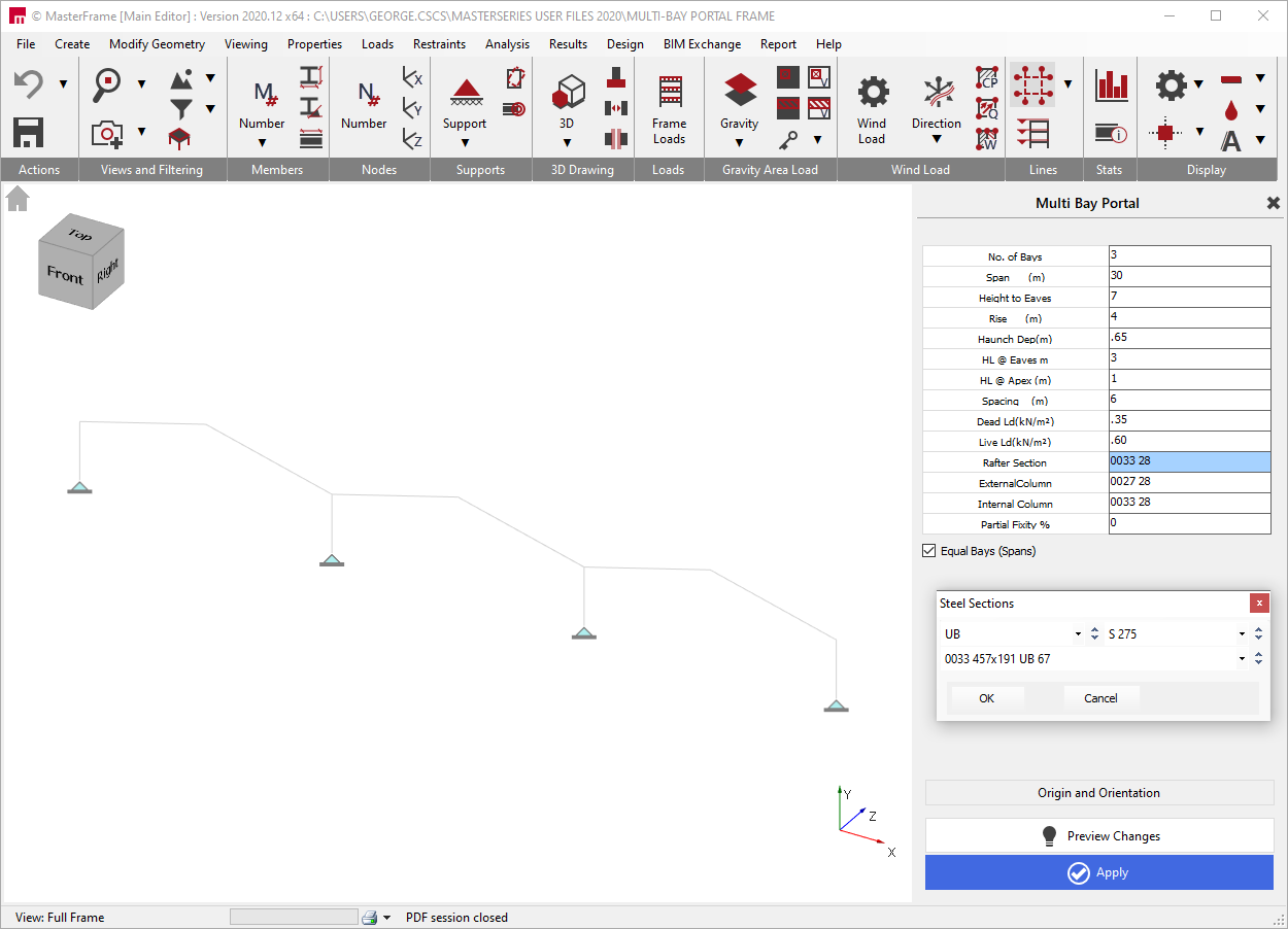
In the Multi-Bay Portal Frame basic data, a single or multi-bay plane portal frame is initially set up. This plane portal frame can later be developed into the 3rd direction to create a full 3 dimensional frame which can be loaded with gravity loads and wind loads.
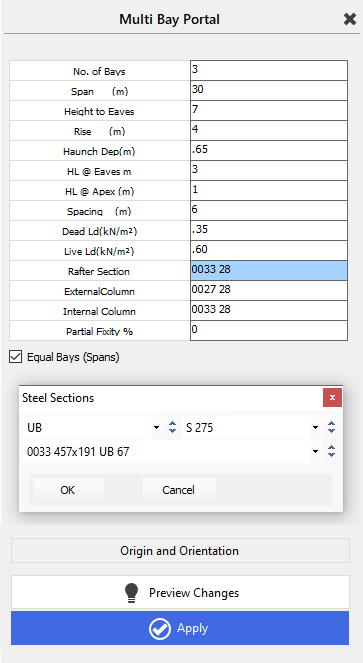
The number of bays across the plane portal frame can be entered and the default span in metres. All the bays will default to this span unless you untick the ‘Equal Bays (Spans)’ box. Unticking the box will open up a droplist containing each of the spans. Move to the appropriate span number and alter its data individually.
The height to eaves and the additional rise to the apex should be entered. Note that these are to the centrelines of member sections for the columns and rafters. If there is to be an eaves haunch, the haunch depth (from the intersection of the column/rafter to the bottom of the haunch where it touches the column flange) and length (on the slope from the centreline of column/rafter intersection to where the haunch touches the rafter bottom flange) are added.
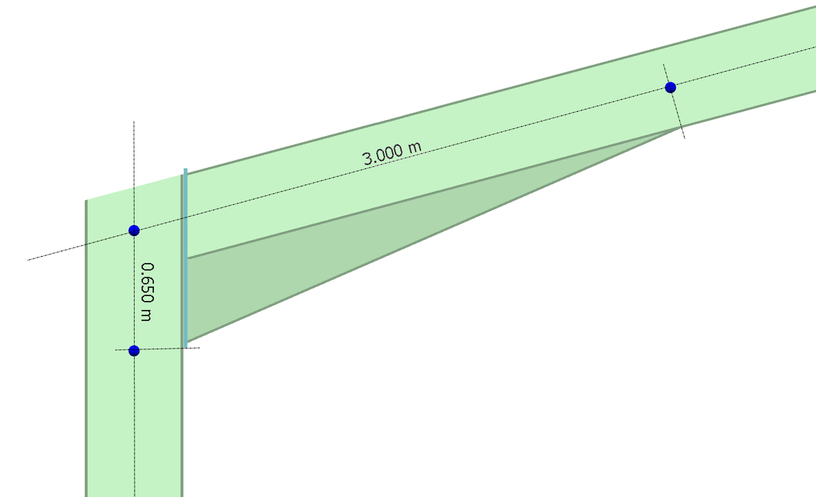
An apex haunch length can also be added (slope dimension from centreline to rafter bottom flange). Enter the spacing between the frames in the 3rd dimension. This is used to calculate the UDL member loads for the Dead and Live loads which are entered as area loads in kN/m2 in plan.
Suggested section sizes for the rafters, external and internal columns are entered along with the base fixity. 0% represents a pinned base and 100% a fixed base. Should you wish to make use of some base fixity for sway and service load combinations, please see section on 📄 Partial Member End Fixity.
If you click on the wording ‘Rafter Section’, ‘External Column’ or ‘Internal Column’ a Steel Sections dialog box will open in which you can select the section type, grade and size for each.
The frame can be added to and manipulated using the functions along the top menu – see the MasterFrame manual for further details.