Top Level Nodes
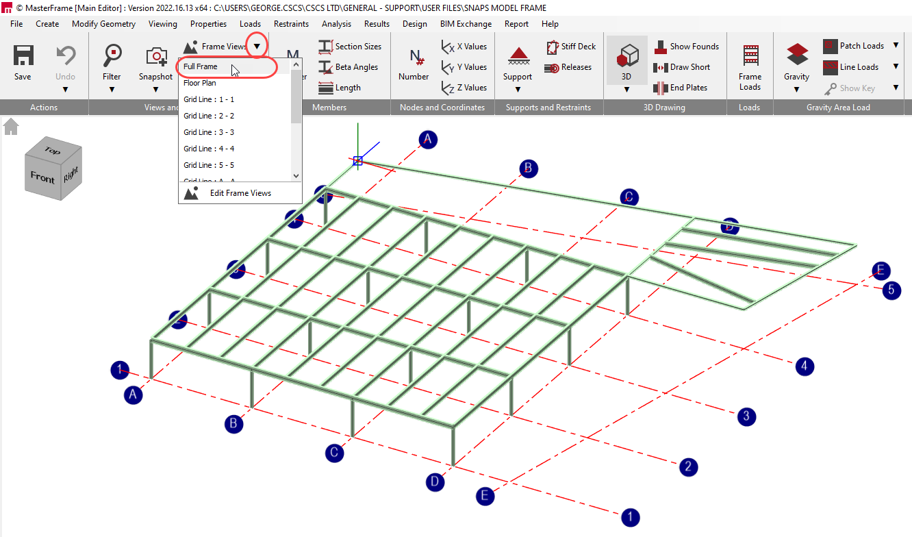
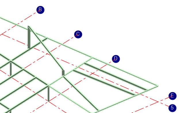
It is possible to create new members between points in a 3D view, eg, columns or diagonal bracing or sloping roof members. To do this we will need to set the frame into a 3D orientation by changing to the full frame view.
However, when doing so it is always worth keeping an eye on the actual coordinate being selected.
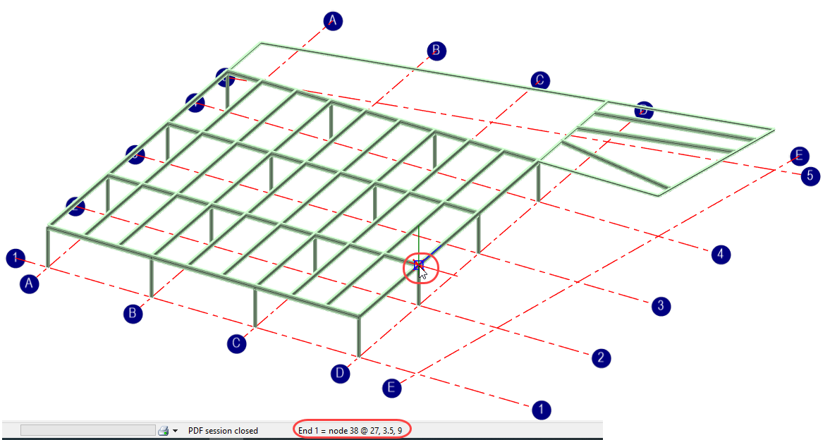
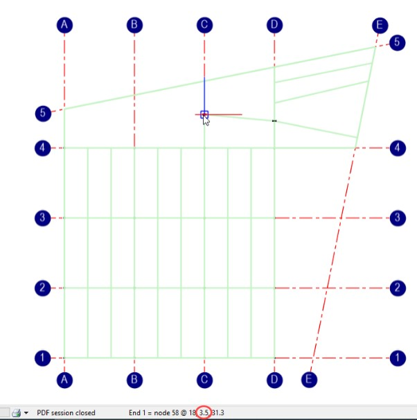
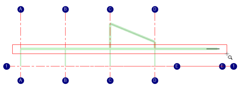
When looking at the full frame back on a plan orientation, the program will always select the point on the frame closest to you. Draw on some more members and add members that are in the vertical orientation so that we now have beams and columns on top of them.
If we reset the structure into the plan view and add a new member from point to point, we would expect to snap to the existing points at the top of Plan at Level 1.
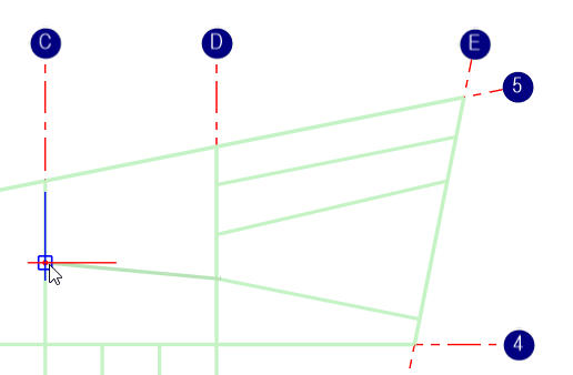
However, we are actually selecting two points at the tops of the new columns because they are the ones that are closest.
So, it is always more useful to operate in one of the views when working in a 2D space.
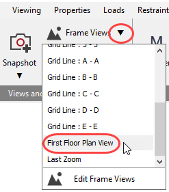
Alternatively, you can use the zoom filter to filter down into a part of the structure you want to work with.
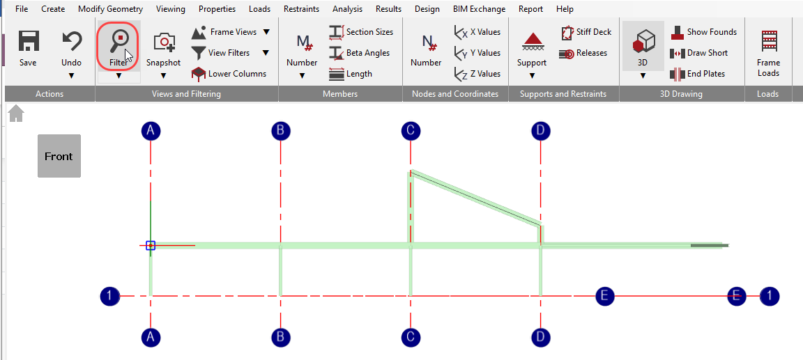
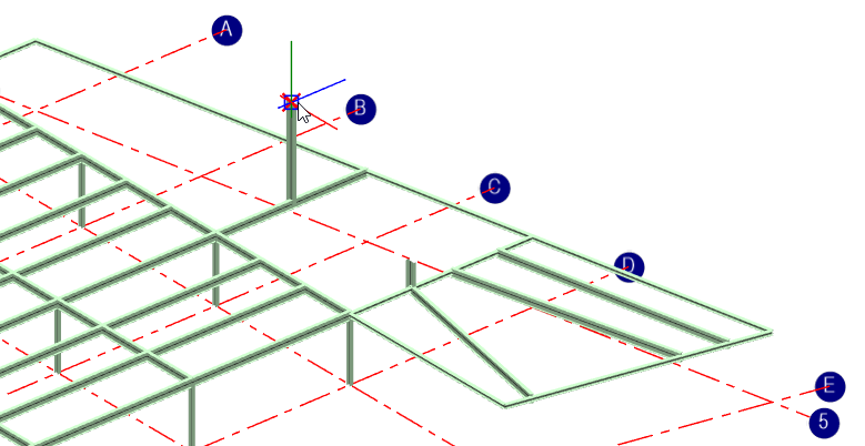
Now we see that the snap does occur at the Y coordinate of 3.5m and the beam goes in at the level that we were expecting it to.