Steel Connections Design Groups (Pro)
Similar to the design group sets above, you can create groups of connections where each group will be designed to use the exact same connection layout for all joints in that group. Thus, connection fabrication costs can be kept to a minimum. The forces and moments from all the ultimate load cases for all the members within the group will be examined together and the optimum solution produced that suits all the criteria.
A useful guidance note has been created titled📄 Steel Connection Design Groups - Integration and Brief Management
Define a Connection Design Group
To define a connections design group:
- Go to Design > Steel Connections Design Groups
- Enter a group name in the drop list, for example, Eaves Joints along Grid Line A
- From the connection type drop down list, select the appropriate connection type
- Select the members to be included in this group
- Add new groups as required
Connection Types
Connection types include:
- Moment : Beam to Column including eaves type
- Moment : Beam to Beam including apex type
- Moment : Base Plate
- Moment : Beam, Column or Hollow Splices
- Simple : Beam to Column Flexible End Plate, Fin Plate or Cleat
- Simple : Beam to Beam Flexible End Plate, Fin Plate or Cleat
The simple connection design for shear only and hence do not require load case compression tolerance settings and the maximum shear force for all grouped beam ends is used in design.
.png)
At Connection Design Stage
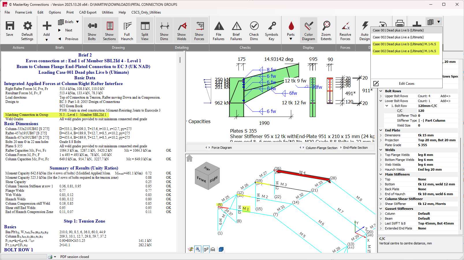
The connection design brief are not created automatically for the connection design group that have been set up. You are required to add a connection design brief of the appropriate type to one of the connection in the group. At this stage the geometry and section section sizes of the current connection are then compared to all the other connection assigned to the group. Only those connection ends with exact matching geometry and section sizes will be included in the grouping.
The forces for all ultimate loads cases for all matched grouped connections ends are then collated and compressed in accordance with he tolerances se tup in the group. This set of 'super ' load cases are then used to design the current connection. For connection that design load case by load case, the complete set of loads cases collated can be viewed in the load case list and is also listed in the design output. For simple connection that are shear only design the maximum shear force from all collated shear forces is used. The member and node number of the load case forces commuted from another connection in the group are appended to the load case title. The match connections in group are also highlighted in red.
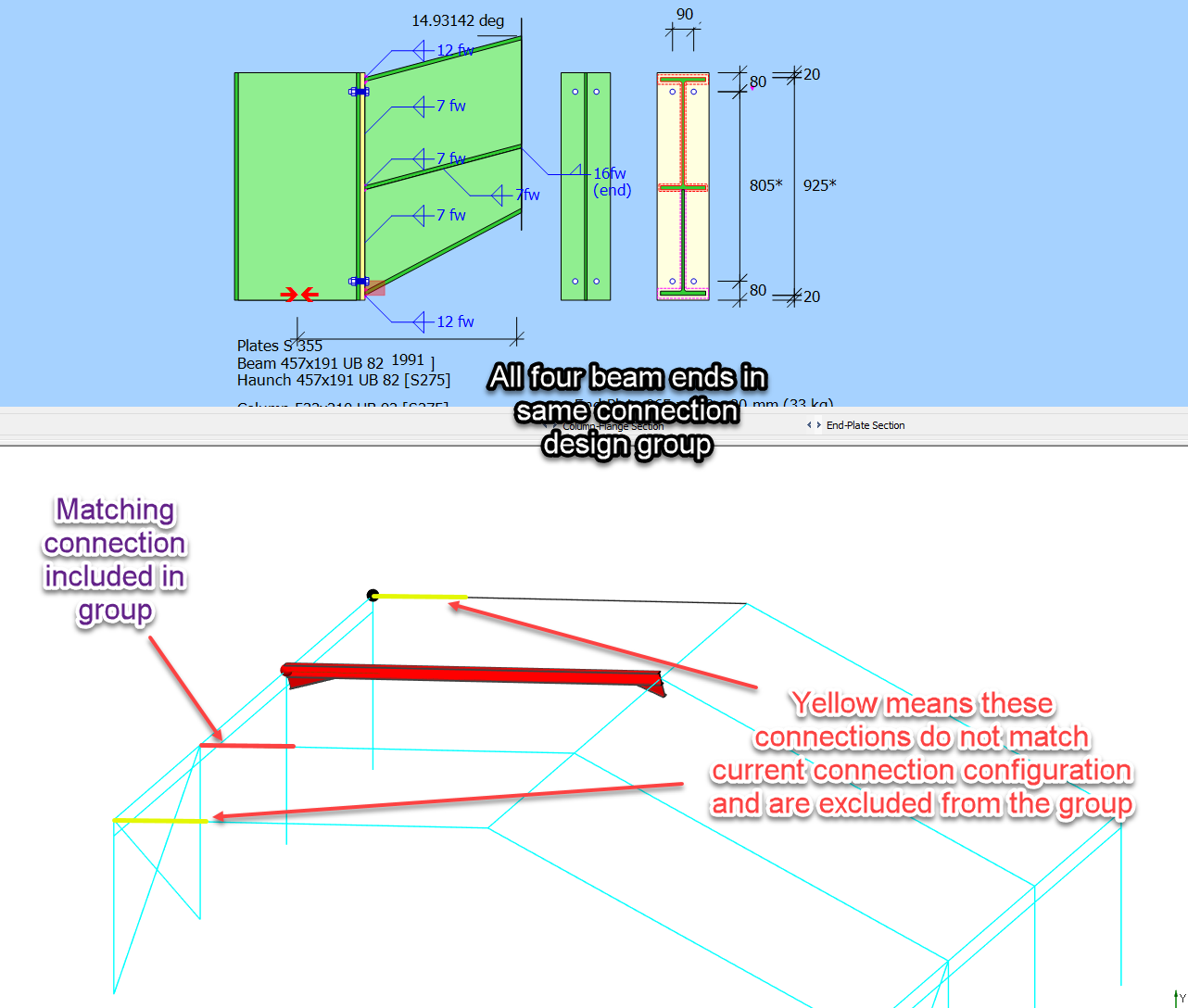
In this way the single connection can be designed that convers the forces condition on multiple member ends and common connection detail can be apply to all ends. There is no need to add further connection design brief to the matching ends as this produce and identical connection configuration and load case set.
In the above example all four rafter ends where added to the same 'Moment: beam to Column' connection group, however the inner two rafter section sizes are different from the gable rafter. Hence the the active connection only matched with the other gable end. In inner two rafter ends are highlighted in yellow to indicate that the are in the same group but have not matched and are not included in the current grouping of forces. Further connection design brief should be added to the yellow ends until all the variation within the group are designed for.