
Load Group – Titles and Code Designation
Structural design codes (British and European) require engineers to evaluate combinations of dead, live, wind, and non-linear/notional actions across both Ultimate Limit State and Serviceability Limit State conditions.
Load Group Concepts and Setup
In MasterSeries, a Load Group is a container for individual load items. Load Groups (e.g., D1, L1, W1) are used to collect and categorize unfactored nominal loads (UDLs, line loads, point loads, density loads) that always occur simultaneously and share the same partial safety factor within any given Load Case.
Load Groups do not apply load factors. Instead, they serve as the building blocks for Load Cases. During analysis, MasterSeries applies appropriate code-based partial safety factors and combination factors to each Load Group depending on the specific limit state being evaluated.
MasterSeries categorizes Load Groups as either Dead Load, Live Load, Wind Load, or Notional Load with a letter prefix followed by a number:
- Dead Loads: D 0-9, A 0-9, B 0-9, C 0-9, E 0-9, F 0-9
- Live Loads: L 0-9, G 0-9, H 0-9, I 0-9, J 0-9, K 0-9
- Wind Loads: W 1-8, P 1-8, S 1-8
- Notional Loads: N 0-9
Notional Load Groups are used for miscellaneous loads that do not fit
neatly into standard dead, live, or wind categories. They behave identically to
any other load group and must be manually factored within your load
combinations. They are also unrelated to Horizontal Notional Loads HNL and EHF.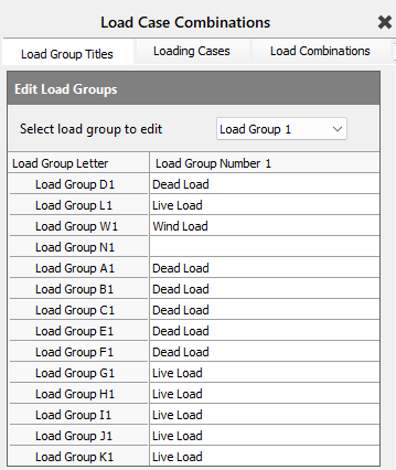
For Live or Imposed Loads (EC0 only) you can choose an Imposed Load Type from the category drop list, see be below.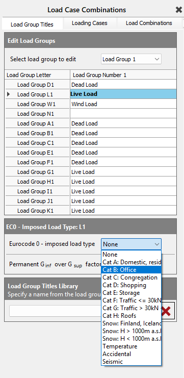
The Unity Load Group (UT) is applied automatically across all Load Cases using a unity partial factor of safety (ie. psf = 1.0). Note that Unity Loads are not explicitly listed inside individual Load Cases, but their forces are included in every Load Case during analysis.
Horizontal Notional Loads (HNL, EHF) are independent lateral forces calculated dynamically per Load Case as a direct percentage of the factored vertical gravity loads to account for frame out-of-plumbness. They are unrelated to static Notional Load Groups N 0-9.
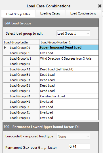
A Permanent Ginf over Gsup factor (favorable / unfavorable) can be set for permanent dead loads. This factor will then be used by the solver and applied to any Permanent Dead Loads marked as Favorable. If left untouched, the default value remains at 1.00 which will have no impact on any favorable dead loads, but if set to say, 1.00/1.35 = 0.74, all favorable dead loads would be reduced accordingly.
Area Panel Routing & Load Group Index Assignment
Area Loading Panel Groups
In the Area Loading Panel Groups editor, MasterSeries provides an efficient framework for distributing floor plate dead and live loads onto supporting beams and columns. While the interface uses standard Load Group prefixes for dead and live load categories, understanding how the software maps these inputs to final Load Group indices is essential for clear model auditing and pattern load configuration.
- Dead Load: D, A, B, C, E, F
- Live Load: L, G, H, I, J, K
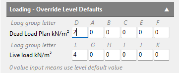
When working with load panels, area loads are defined strictly using these category letters without a Load group index. The actual numerical Load Group index (0–9) applies at the supporting member level, not the panel level. By default, MasterSeries routes all panel dead and live loads to their associated supporting members using Load Group 1 (e.g., D1, L1, A1, G1).
To route loads using Alternative Load Group indices for pattern loading, the Engineer must assign the supporting members to an Alternate Load Group (0-9). The Alternate Load Groups editor will enforce a unified group load index for any given member, such as D2/L2 or D3/L3. In this selection menu, the letters ‘D’ and ‘L’ do not refer specifically to load groups D and L, but rather represent the Dead and Live categories generally. Selecting Load Group D2 L2, automatically routes all of the superimposed dead loads, and live loads collected by that member's tributary area to Load Group 2.

Default Loading and Construction per Level
The Default Loading and Construction per Level editor allows the designer to establish a unified floor-wide slab depth and concrete density (from which the slab self-weight is automatically calculated) along with default superimposed dead and live load intensities on a level-by-level basis.
- Slab Load: D, A, B, C, E, F
- Dead Load: D, A, B, C, E, F
- Live Load: L, G, H, I, J, K
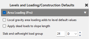
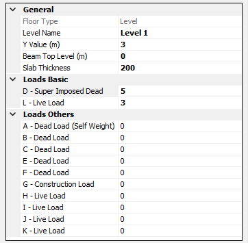
By default, all Global Level Loads are routed directly to Load Group 1. To implement patterned loading, the Engineer can assign supporting boundary members to alternative indices (0–9) using the Alternate Load Groups editor.
As before, the Alternate Load Groups editor will enforce a unified group load index for any given member, such as D2/L2 or D3/L3. In this selection menu, the letters ‘D’ and ‘L’ do not refer specifically to load groups D and L, but rather represent the Dead and Live categories generally. Selecting Load Group D2 L2, automatically routes the slab self-weight, and all of the superimposed dead loads and live loads collected by that member's tributary area to Load Group 2.
Any slab definitions, dead loads, or live loads defined directly within the Area Loading Panel Groups editor will override and replace the corresponding Level Default for those specific panels.
FE Alternate Loading, Load Sets, and Spatial Patterning
To evaluate peak hogging, sagging, and shear envelopes across continuous beams and floor grids, structural design codes require variable actions and, occasionally, dead loads to be patterned across alternate and adjacent spans.
MasterSeries manages spatial load patterning by combining Load Group prefixes DA, LA, etc. with FE Load Sets 0-9. When combined, MasterSeries then directly routes the Alternate Load Group to the assigned Load Set 0-9.
- DA assigned to Load Set 1 routes to the D1 Load Group.
- DA assigned to Load Set 2 routes to the D2 Load Group.
- DA assigned to Load Set 0 routes to the D0 Load Group.
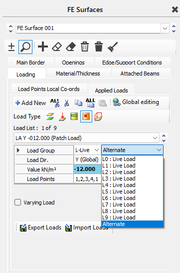
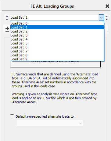
It is good practice to route your superimposed loads through Load Sets 1–9 only, and not through Load Set 0. Load Group D0 is generally dedicated to global structural self-weight and static, non-patterned continuous actions. For example, routing superimposed dead loads through Load Set 0 makes auditing your Load Cases (and load patterns) more difficult as you will end up with superimposed dead loads merged into the same Load Case as global member self-weights.
Where you need to alternate the self-weight (gravity), best practice is to set the density/gravity load as DA and then route it through Load Sets 1-9. This gives you more control over the patterned loading and cleaner Load Cases.
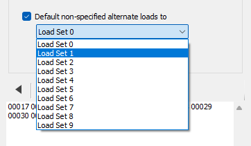
MasterSeries can also route any alternate/patterned loads (DA, LA, etc.) to a default Load Set, where an explicit Load Set number has not been assigned.
Composite Load Cases
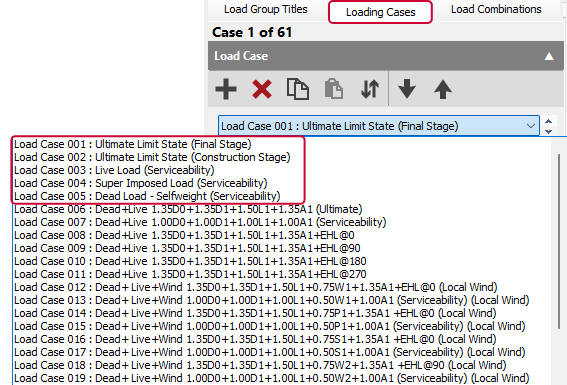
Composite floor design requires separating temporary construction actions on the bare steel frame from permanent, long-term composite actions. Applying Eurocode rules, MasterSeries reserves and hard-codes Load Cases 001–005 to perform the required two-stage analysis. These reserved cases cannot be manually overwritten:
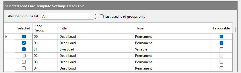
- Load Case 001: Ultimate Limit State (Final Stage): 1.35 D0 + 1.35 D1 + 1.50 L1 + 1.35 A1
- Load Case 002: Ultimate Limit State (Construction Stage): 1.35 D0 + 1.35 A1 + 1.50 G1
- Load Case 003: Live Load (Serviceability): 1.00 L1
- Load Case 004: Superimposed Load (Serviceability): 1.00 D1
- Load Case 005: Dead Load - Selfweight (Serviceability): 1.00 D0 + 1.00 A1
Automatic Load Group Routing for Composite Design
To generate these reserved composite cases without requiring manual re-assignment, MasterSeries automatically splits member self-weight routing inside Global Data as follows:

Columns
Retained within D0 so primary vertical support members remain continuously loaded across all Stage 1 and Stage 2 load cases.
Beams and Composite Slabs
Automatically re-routed (from D1) to A1 (Dead Load - Self Weight). This isolates floor framing self-weight so it is evaluated against the unpropped steel section in Stage 1 construction cases (Load Cases 002 and 005).
Finite Element Mesh
Slab mesh self-weight remains within D1, keeping horizontal surface dead loads separated from vertical column self-weight.
Construction Live Load
In addition to the above, MasterSeries automatically utilizes Load Group G1 for temporary Stage 1 construction live loads.
Horizontal Notional Loads (HNL / EHF)
Structural design codes (such as Eurocode BS EN 1993-1-1 and BS 5950) require global frames to be designed for the effects of sway imperfections and initial out-of-plumbness. In MasterSeries, these lateral sway effects are applied using Horizontal Notional Loads (HNL), also referred to as Equivalent Horizontal Forces (EHF).
Unlike static gravity or wind loads assigned to
explicit load groups (D0, L1, W1), MasterSeries calculates and applies HNLs
dynamically at run-time based on the active gravity combinations.
Dynamic Generation vs. Static Notional Load Groups
A common point of confusion in MasterSeries is the distinction between dynamic HNL/EHF forces and static Load Groups N 0-9:
Dynamic HNL / EHF
Calculated automatically during the solver pass. MasterSeries evaluates the total factored vertical gravity load active in a given Load Case and applies a design code percentage (typically 0.5% under Eurocode rules, adjusted for height and column count) as lateral forces applied at each beam/column node or floor level.
Static N 0–9 Load Groups
Placing a load manually into N 0-9 creates a fixed, static force item that must be explicitly added and factored within your Load Case combinations.
Do not confuse static N 0-9 load groups with dynamic HNLs.
Real frame out-of-plumbness checks should always rely on MasterSeries'
automated HNL/EHF generator rather than manual N group entries.
Directional Combinations & Structural Orthogonality
Sway imperfections can act in either global horizontal direction (+X, -X, +Z, -Z). Because HNLs depend directly on the vertical load present in each specific load combination, MasterSeries handles directional sway logic across your Load Cases as follows:
Gravity-Dominant Combinations (ULS)
HNLs are evaluated concurrently with full vertical ULS combinations to ensure the frame possesses adequate lateral stability against initial imperfection sway without wind.
Wind-Dominant Combinations
Under Eurocode provisions, where horizontal wind forces exceed a significant threshold relative to sway imperfections, dynamic HNLs may be automatically omitted or combined based on code-specific sway sensitivity checks.
Directional Sign Permutations
The solver applies the calculated lateral load in +X, -X, +Z, and -Z directions to capture critical column moment amplifications and core wall shear forces.
Conclusion
MasterSeries' automated combination engine and two-stage stiffness solvers eliminate a lot of manual calculations, but they rely strictly on clean input data. By adhering to well established, best modeling practices, such as isolating floor panel definitions within Load Sets 1–9, leaving reserved Composite Cases 001–005 untouched, and leveraging dynamic HNL generation, Engineers can maintain total auditing clarity over their models. Following this architecture guarantees that global analysis runs smoothly, Stage 1 construction checks remain isolated from long-term serviceability checks, and structural design checks remain fully compliant with governing design standards.