FE Surface Alternate Pattern Loading
When determining the Ultimate envelope of forces for slab design, it is normally required to consider various arrangements of loading in order to develop the most critical stresses in each area of the slab.
BS 8110 Pt 1 [3] suggests that it is normally sufficient to consider the following arrangements:-
- All spans loaded with maximum factored design ultimate load, 1.4 x Dead + 1.6 x Live.
- Alternate spans loaded with the maximum, 1.4 x Dead + 1.6 x Live, and all other spans loaded with 1.0 x Dead.
While BS EN 1992-1-1 suggests that it is normally sufficient to consider the following arrangements:-
- All spans loaded with maximum factored design ultimate load, 1.35 x Dead + 1.5 x Live.
- Alternate spans loaded with the maximum, 1.35 x Dead + 1.5 x Live, and all other spans loaded with 1.35 x Dead.
In the case of a slab this principal can be applied in two perpendicular directions in order to produce the critical forces in two directions, e.g. Mx and My. Hence any slab needs to be divided into strips (between columns) in one direction and also strips in the approximate perpendicular direction, as shown below.
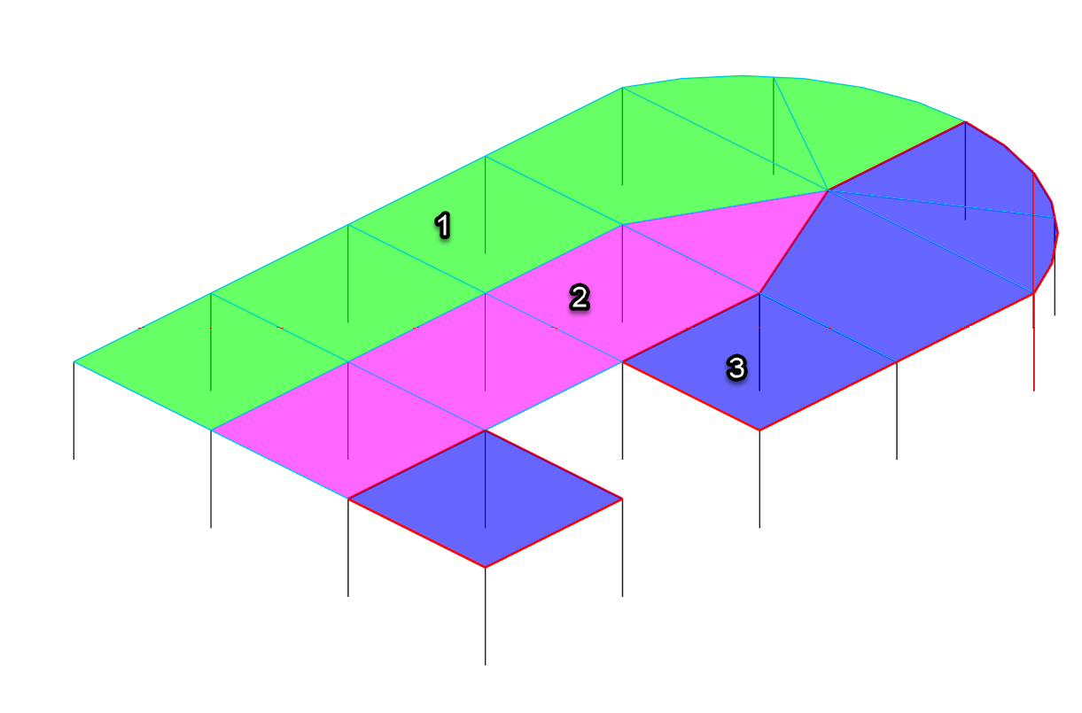
Direction 1 patterning
Using the above arrangement of strips the following loading cases could be produced in to ensure the maximum sagging moment is developed in each span.
Patterning in direction 1
1. Max 1 + Min 2 + Max 3
2. Min 1 + Max 2 + Min 3
3. Max 1 + Max 2 + Min 3
4. Min 1 + Max 2 + Max 3
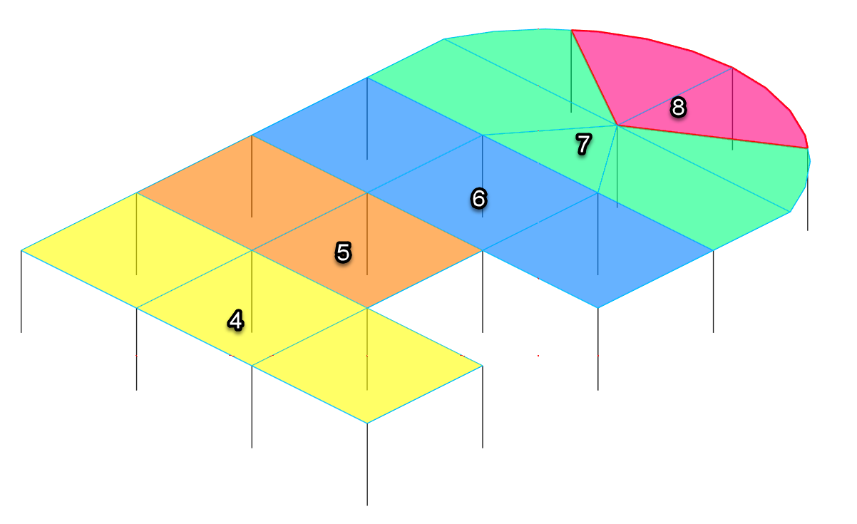
Patterning in direction 2
5. Max 4 + Min 5 + Max 6 + Min 7 + Max 8
6. Min 4 + Max 5 + Min 6 + Max 7 + Min 8
Loading cases 3 and 4 are necessary to produce an alternate condition of loading at the north of the slab (where strips 1 and 3 are adjacent to each other). Note that strips 1-3 are never combined with strips 4-8, since this would create an overlapping of the same areas.
In the MasterFrame FE Editor these strips can be assigned load set numbers from 0 to 9. This range is used because in MasterFrame each load type can have numbers 0 to 9, i.e. D0 to D9, L0 to L9 etc. Only the load set number is assigned to a strip and not the load group type, i.e. D, L, W etc. The load set numbers will inform any D, L, W etc. surface loads that have been applied (using a special load set) as to which final load group that load will be used in.
Therefore adequately define alternating (patterned) loading for FE Surfaces in MasterFrame, three steps are required.
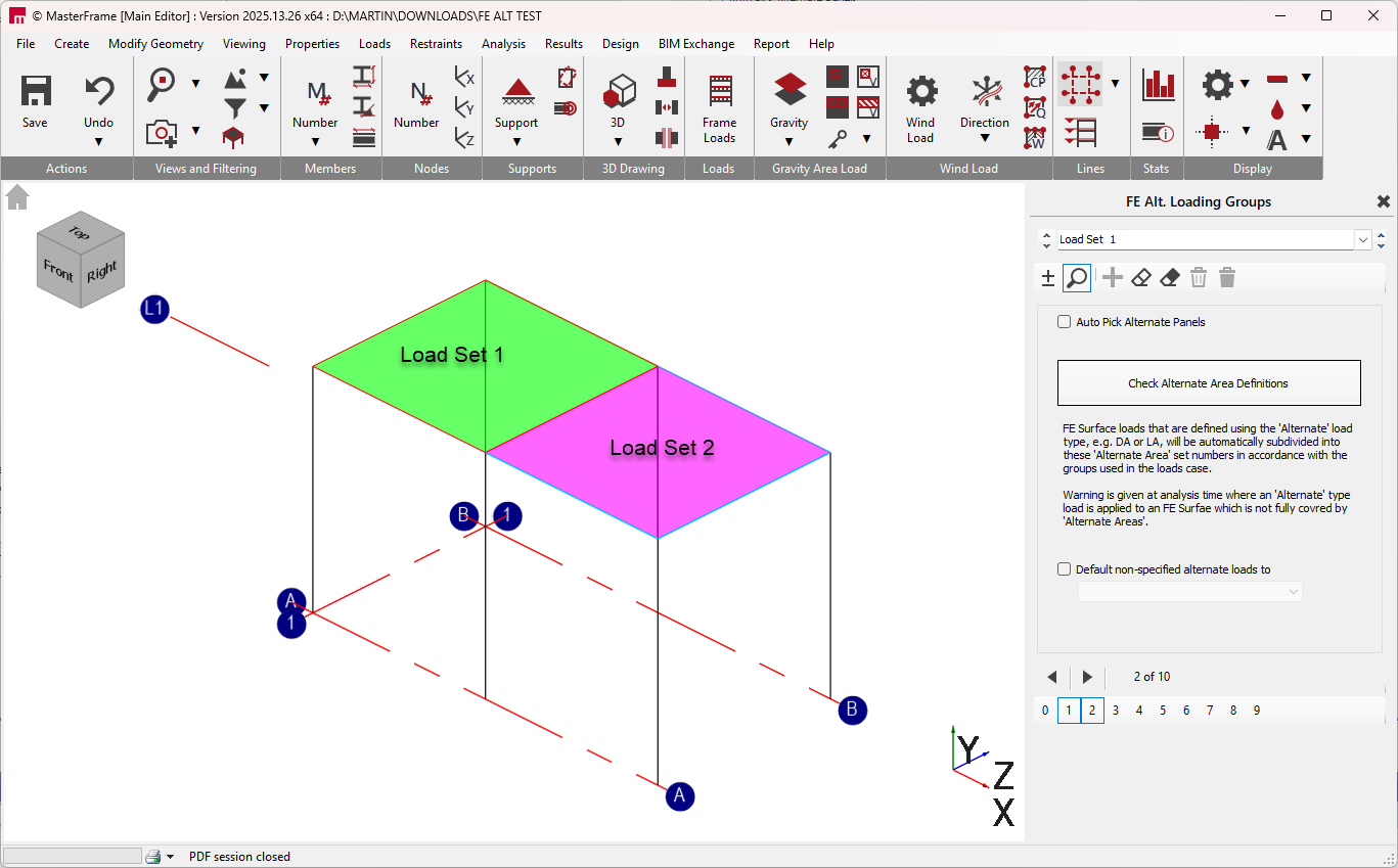
- Defining FE Alternate Area Load Group Set Number Regions - these determine how 'Alternate' type designated loads are to be split up into load group numbers and different patterns of alternation to be considered.
- Select which FE Surface loads are to observe these FE Alternate Area Load Group Set Number Regions as 'Alternate type
- Set up load load cases with appropriate patterned Max/min, Min/Max load facto patters in accordance with the patterned areas defined in step 1.
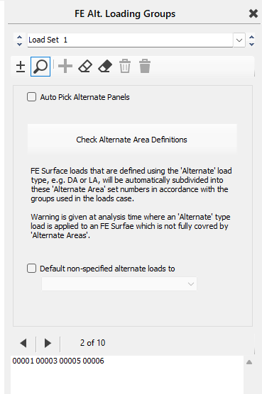
Defining FE Alternate Area Load Group Set Number Regions
To assign load set numbers to the strips in the slab:-
- Select ‘Loads> FE Surface Alternate Loading Patterns ’ from the top menu bar.
- Ensure that the add/remove mode
is active by clicking on the
 button.
 - Select the load set number that you wish to use from the drop list.
- Click on the boundary members of the strip or strips that you wish to associate with this load set.
Therefore, as indicated in step 4 above, it necessary to provide members between column heads to facilitate the definition of a strip. The boundary members selected must form a closed loop. The area of the strip(s) will be drawn in colour when correctly defined.
It is important to realise that it is not necessary to use a separate load set number for each strip. If this were the case the load sets 0 to 9 would be insufficient, since in many instances there would be more than 10 strips. Separate strips can use the same load set number provided that they are not adjacent to each other or overlapping. In the above example it can be seen that in any one loading case strips 4, 6 and 8 always use the same factoring (max or min), as do strips 5 and 7. Hence the following load sets could be used in this example.
|
Strip Number |
1 |
2 |
3 |
4 |
5 |
6 |
7 |
8 |
|
Load Set Number |
1 |
2 |
3 |
4 |
5 |
4 |
5 |
4 |
Hence in terms of load set numbers for load cases, this becomes
- Max 1 + Min 2 + Max 3
- Min 1 + Max 2 + Min 3
- Max 1 + Max 2 + Min 3
- Min 1 + Max 2 + Max 3
- Max 4 + Min 5
- Min 4 + Max 5

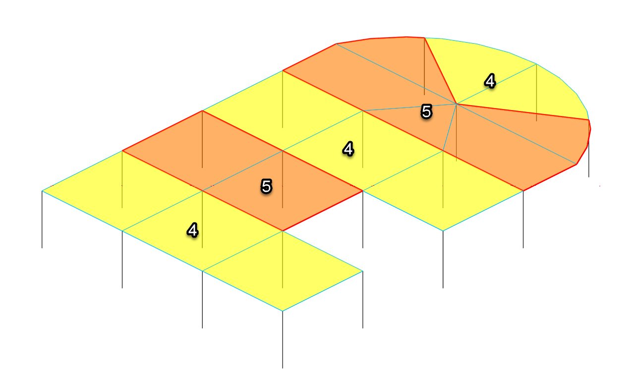
A Max 1 + Max 2 + Max 3 case can also be included to all spans loaded with full load factor. There would be no requirement to have a Max 4 + Max 5 as this would be identical.
The 'Default non-specified alternate loads to' setting can be used to select a default load set number for FE surface regions in which no specific region have been defined. A useful application of this is where you have wall surfaces and also have the global density load defined as DA (see below), in this case the wall self weight will require alternate load set regions to determine the load set number to use. To avoid having to set these up you can default them to say load set 0 (or any other load set number not used the main patterning purposes). The wall self weight will then be attributed to D0 and the D0 load group can be used in all load cases with patterning. See 'No Alternate Load Set Region Error' below.
Designating FE Surface Loads to observe the Alternate Area Load Set Nu. Inmber Regions
Important! - When applying the loads to a surface, any load that is to be used in accordance with the load set numbers assigned to the strips must be defined as an ‘Alternate’ load, from the load set drop list as shown.

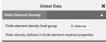
The ‘Alternate’ option may also be chosen for the global density load group in the ‘Loads> Density for Self Weight...’ area.
Setting Up the Load Cases to Activate the Appropriate Patterns
Loading cases with appropriate load combination can then set set up to utilize these load groups in a pattered alternate manner in accordance with the design standard requirement. For example for Eurocode this might be
Patterned in one direction
1. 1.35 D1 + 1.5 L1 + 1.35 D2 + 1.35 D3 + 1.5 L3 - note no L2 is included
2. 1.35 D1 + 1.35 D2 + 1.5 L2 + 1.35 D3
3. 1.35 D1 + 1.5 L1 + 1.35 D2 + 1.5 L2 + 1.35 D3
4. 1.35 D1 + 1.35D2 + 1.5 L2 + 1.35 D3 + 1.5 L3
Patterned in a perpendicular direction
5. 1.35 D4 + 1.5 L4 + 1.35 D5
6. 1.35 D4 + 1.35 D5 + 1.5 L5
Eurocode Simplified Arrangement (2025.13.28+)
Note - Version prior of 2025.13.28 expected both the Dead and Live loading to defined as Alternate, i.e.. DA and LA. For Eurocode then the D alternate load set would then all be set up with he same load factor as above.
From version 2025.13.28 this requirement has been changed. Since Eurocode does not call for patterning of the permanent (dead) loading it is now possible leave the global self-weight dead load and applied surface dead load as D1 for example and not DA, and only using the Alternate load type for variable (Live ) loads, i.e. LA. In this way the arrangement of the above loads cases can be simplified to .
- 1.35 D1 + 1.5 L1 + 1.5 L3 - note no L2 is included
- 1.35 D1 + 1.5 L2
- 1.35 D1 + 1.5 L1 + 1.5 L2
- 1.35 D1 + 1.5 L2 + 1.5 L3
- 1.35 D1 + 1.5 L4
- 1.35 D1 + 1.5 L5
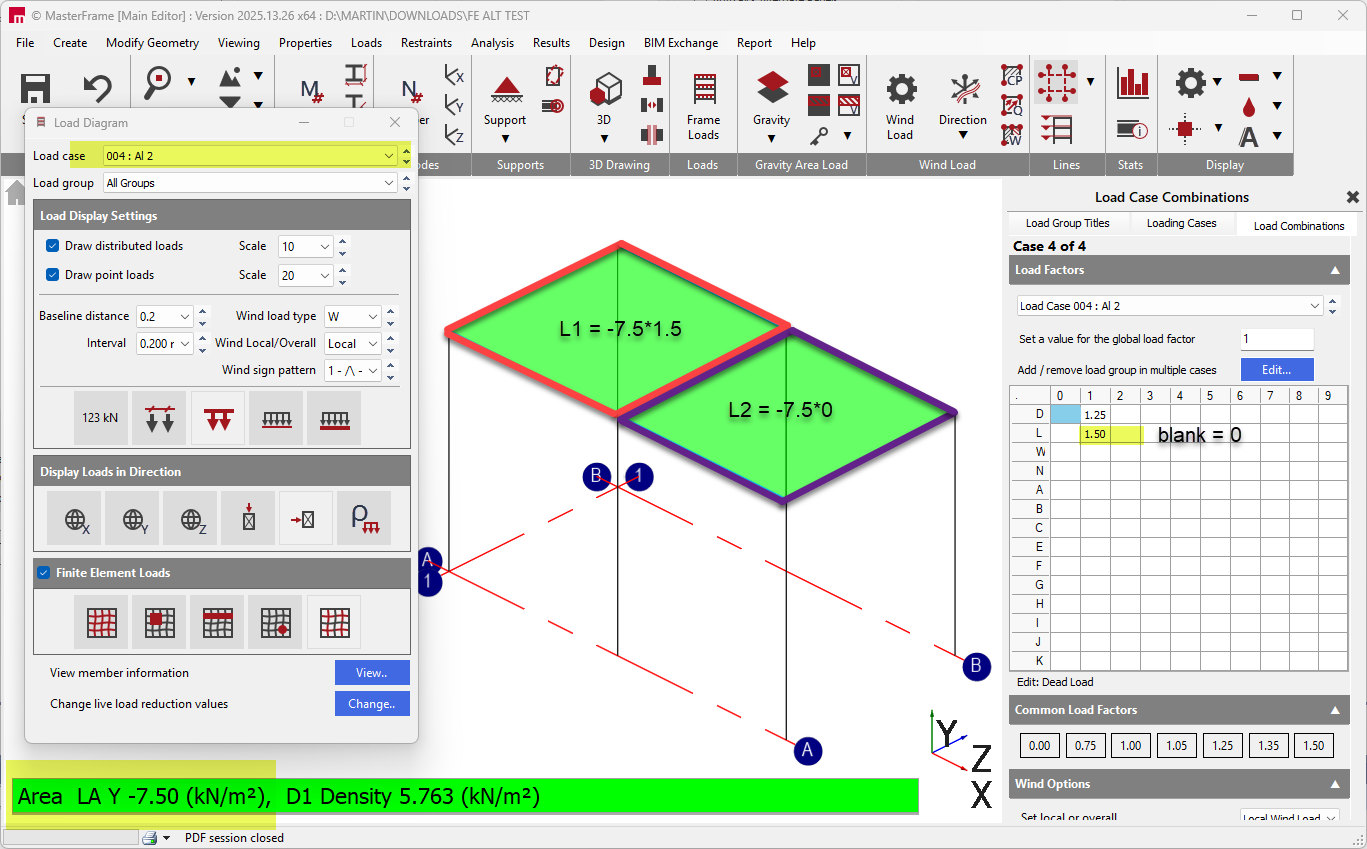
Viewing Loads Per Case Graphically
|
From the standard MasterFrame frame load diagram the Alternate load button can be used to display the alternate areas that are involved in the currently selected loading case.
|
|

Please note that the 'Alternate' type loads are not subdivided into their alternate load groups in this view. For example if an FE Surface has an LA area load, FE Alternate Area Load Group Set numbers 1 and 2 used in strips to pattern, and in the case we have L1 factor =1.5 and L2 factor = 0, the load will be displayed as it's unfactored LA value and not it subdivided into it's factor L1 and L2 parts. This subdivision is reserved for analysis time.
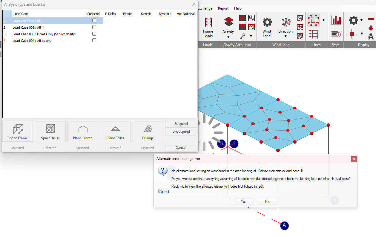
No Alternate Load Set Region Error
If you apply a 'Alternate' type load, .e.g. LA to an FE Surface, but not fully define the 'FE Alternate Area Load Group Set Number Regions' within this surface, the LA load in these undetermined regions will not know which load group number to use. This is presented as an error, with the option to continue using the leading load group factor for the undetermined area.
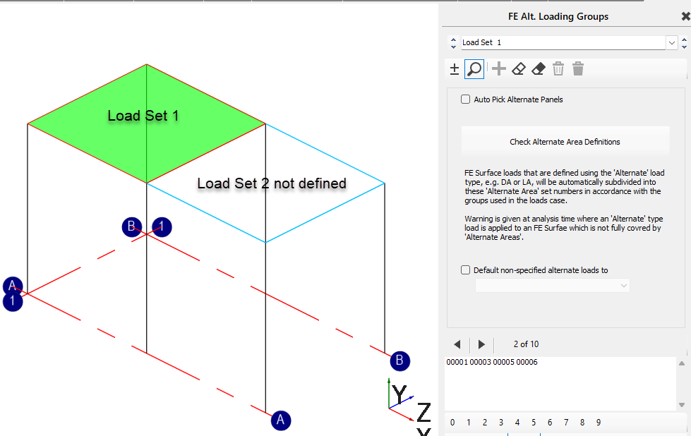
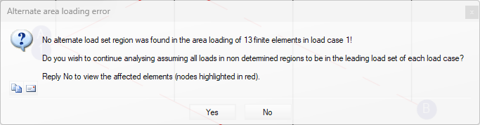
Replying 'No' will abort the analysis and highlight the affected area.
Replying 'Yes' the analysis will continue using and use any leading load factor for the undetermined area.
In this example load case 1 has L1 factor =1.5 and L2 factor = 0. Since the intended L2 part cannot be determined it will use the same load factor as L1. This is not the intended pattern for this case. The 'FE Alternate Area Load Group Set Number' as Load Set 2 should be defined for the missing area.
The above behaviour for the 'No Alternate Load Set Region' applies to version 2025.13.28 onwards. Prior versions had requirements for both Dead and Live being set as 'Alternate' and the error may have occurred in other arrangements.