FE Raft Slab Tutorial
Analysing and Designing a Raft Slab using FE and Concrete Slab Design.
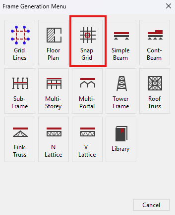
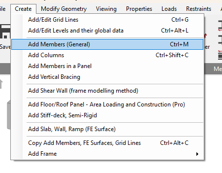
The Frame Generation Menu
In most cases, you will be able to select a start-up frame and then tailor it to your specific requirements. In this case, we shall generate Grid lines.
The Frame Generation Menu (Frame Wizard) is now displayed as shown.
Select the Snap Grid.
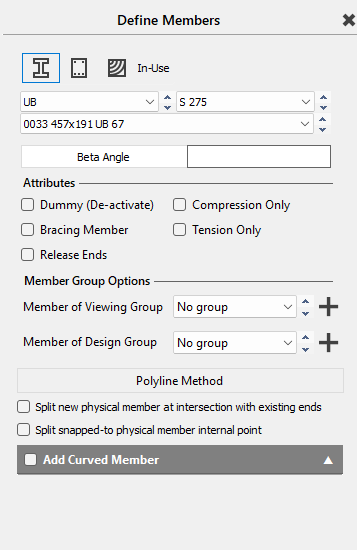
Defining Members
Keep it as the Default shown below.
For more information click HERE
 Chapter 3 MasterFrame - 3.3.1 Frame Generation
Procedures and Templates
Chapter 3 MasterFrame - 3.3.1 Frame Generation
Procedures and Templates
This tutorial describes some of the basic techniques used in MasterFrame. Please take a few minutes to familiarise yourself with the various frame viewing tools; editing and data input methods and find how you can use the modify geometry area to select members.
Setting up the Raft Geometry
Before we start creating the members, place the snap grid in
Top view by selecting the Top side of
the viewing cube (. )
)
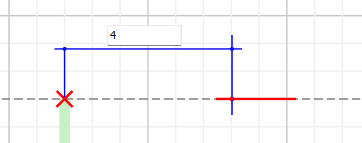
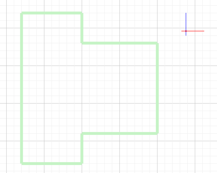
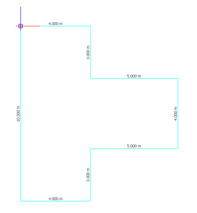
Draw a vertical member from the origin 10m in length shown below.
At the ends of the above member, Add a member that's 4m to the right of the member.
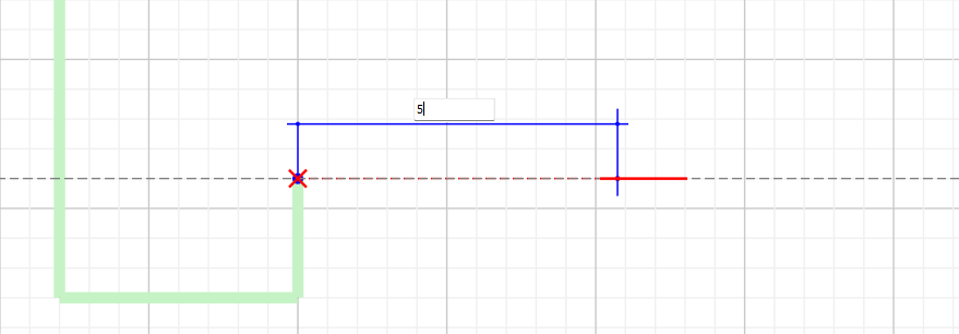
From the end of the previous member continue 3m down grid line, then draw a member that is 5 m long and mirror the set up on the opposite side
Applying FE surface Properties
Navigate to Add slab, Wall, Ramp ( FE surface), under the create menu.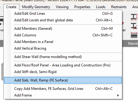
Using this feature we will add the FE properties to the generated slab geometry.
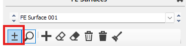
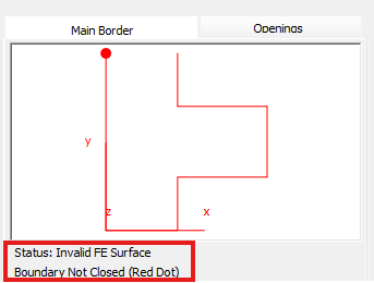
Using the add button window select the boundary members of the panel until you get a valid FE surface. If an open area or invalid are is selected, the window shows invalid FE surface status.
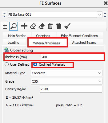
Add slab properties, Using the Materials/Thickness tab , under the same window, we will set the Thickness to 200mm.
Ensure that Codified Materials is selected, select the concrete option and set the grade to C35.
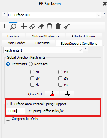
The next thing we need to set is the Support conditions, Using Full Surface Area Vertical Spring Support, under the edge/support conditions tab, set the Y spring Stiffness to 10,000kN/m^3. This is to represent the soil type (soft clay or loose sand) and will help simulate real life loading.
Loading
Next we are going to apply the loading to our Slab, Staying in the FE Surfaces tab, move to the loading section.
- Line Loads: Typically used for walls bearing onto the raft. You define these by picking points on the FE surface (Load Points). Line loads are input in kN/m.
- Point Loads: For concentrated loads from columns not explicitly modelled as 1D members intersecting the slab. Point loads are input in kN.
- Patch Loads: For distributed loads over a specific part of the raft area. Input in kN/m².
- Perimeter Loads: For loads acting along the edge of the FE surface.
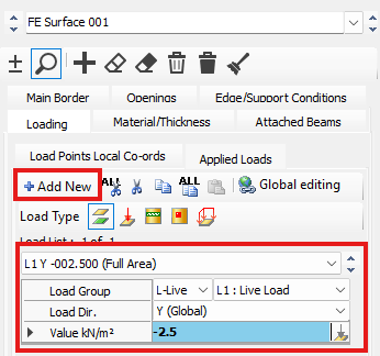
Press the Add New button, change it to a live load (L1), with a Value of -2.5. This is the load acting over the entire surface. This is for a Uniformly distributed load over the entire raft.
Next we need to add the line loads acting on this slab. Turn on Node Number ( ) to help Navigate the location of each load.
Tip: Alternate Load Patterns: For rafts, especially those supporting continuous walls or spanning between points, using alternate load patterns is essential for capturing worst-case bending moments (both sagging and hogging). This involves designating load sets that can be applied in different combinations. For example, you can define load sets for adjacent strips that will be loaded alternately (e.g., Max-Min-Max-Min). This helps simulate scenarios that maximise moments at different locations.
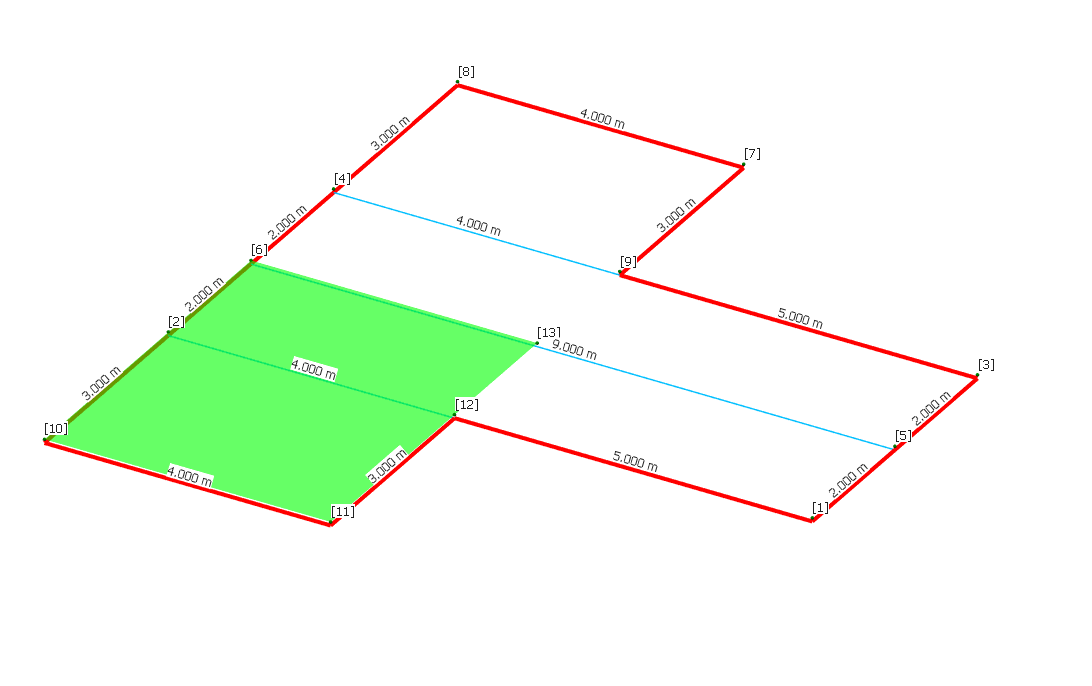
Creating an alternate area
Slab loads does not act uniformly throughout the slab surface always. So an alternate loading surface has to be defined for this alternate loading action.
Go back to Create>Add new Members, Draw 3 new Members Spanning from Node 2-8, Node 4-9 and 3-11.

Load Cases
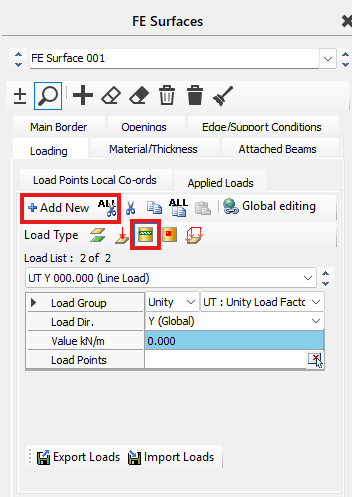
Now we are going to add more loads. Go to Modify Geometry and click on Edit FE Surface.
Add a new load and click on line load.
All further load cases will be Alternate as slabs loading doesn't always act uniformly.
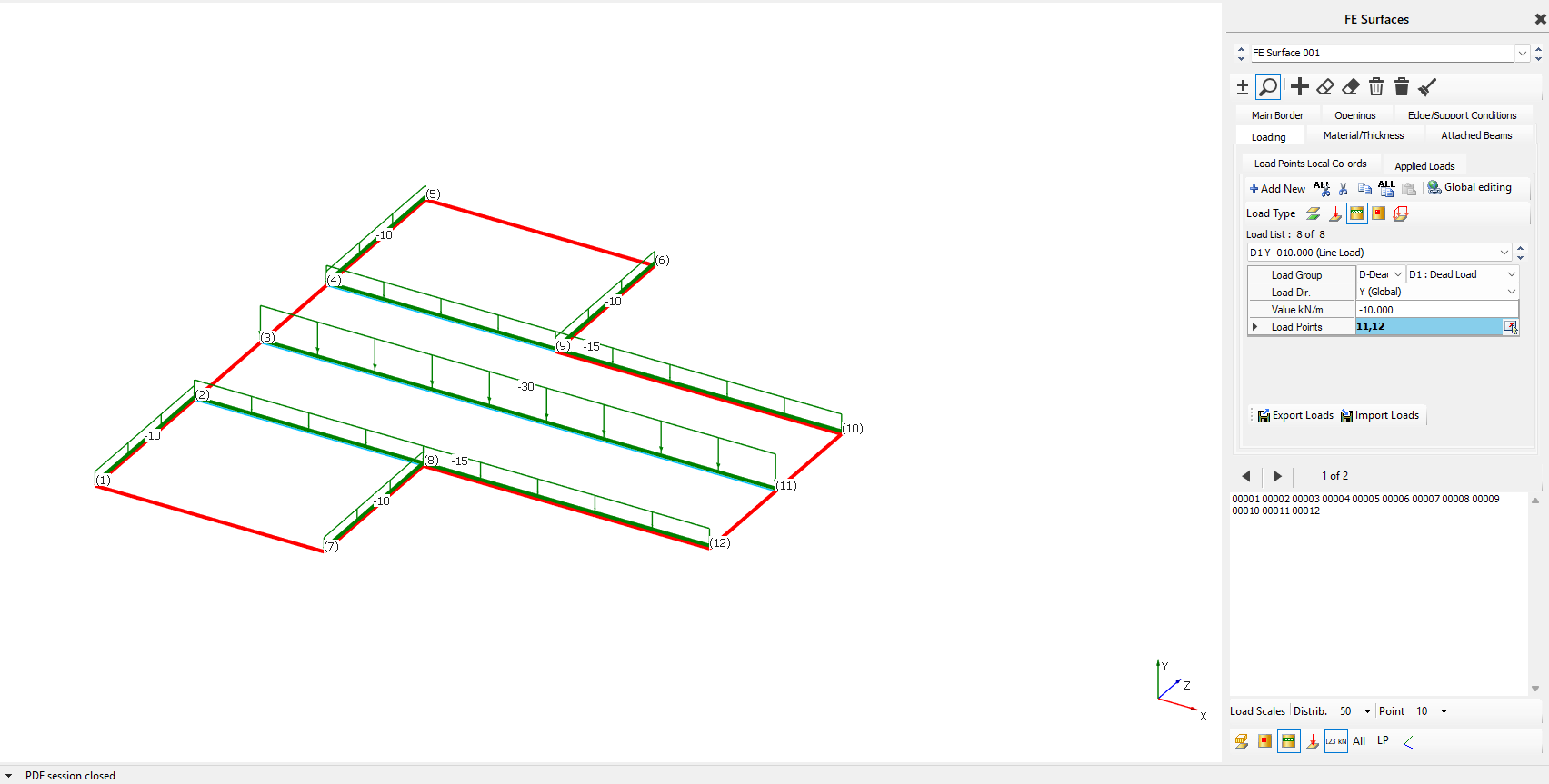
First we add Dead Load:
- Dead Load- -15.000, Nodes 2-12
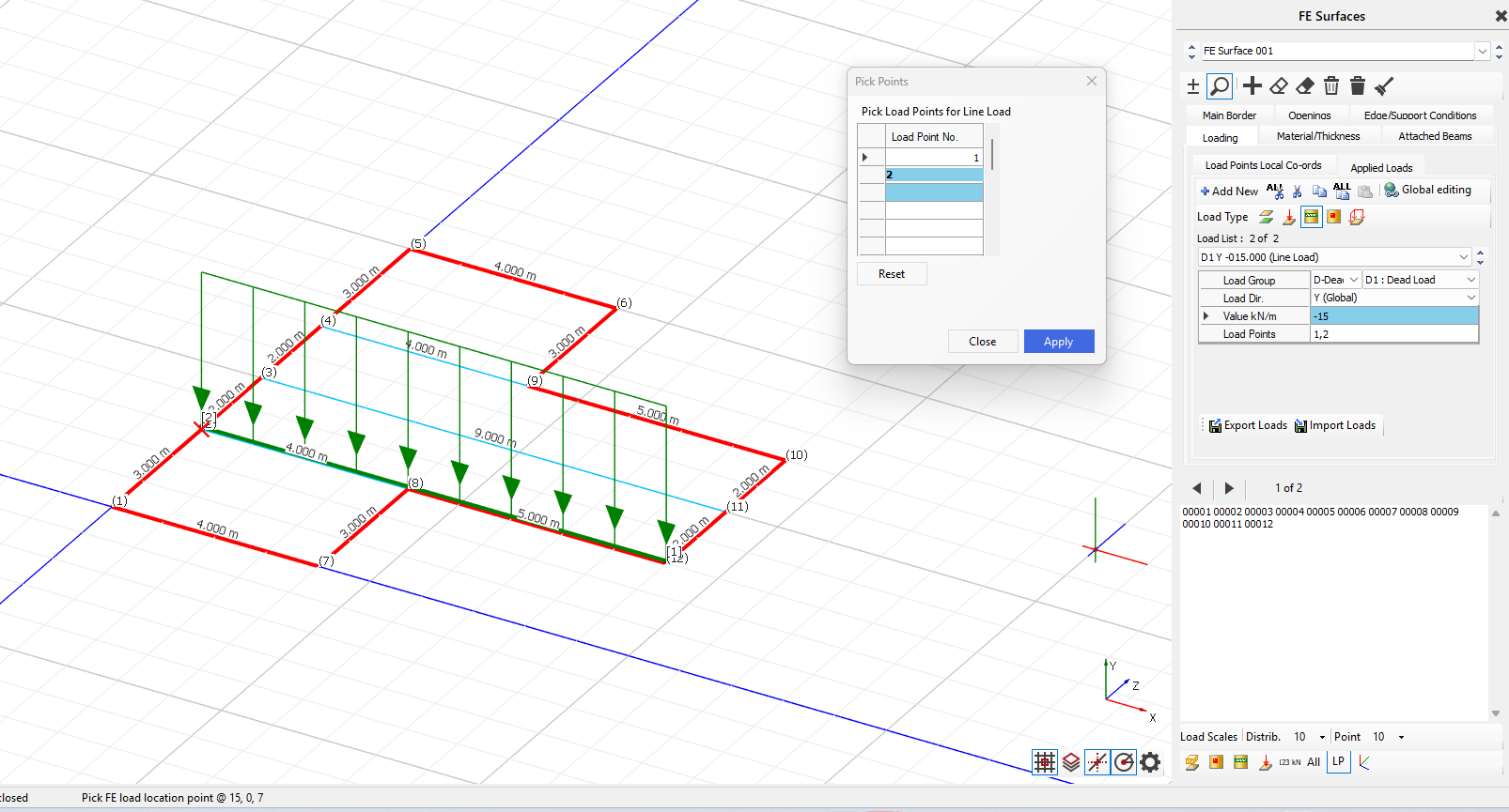
- Dead Load, -15.000, Nodes 4-10
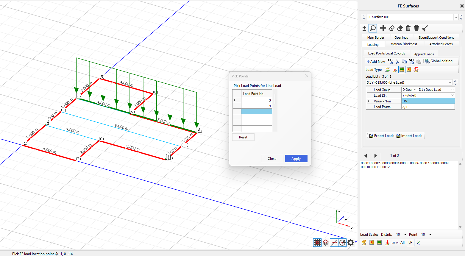
- Dead Load, -30.000, Nodes 6-11
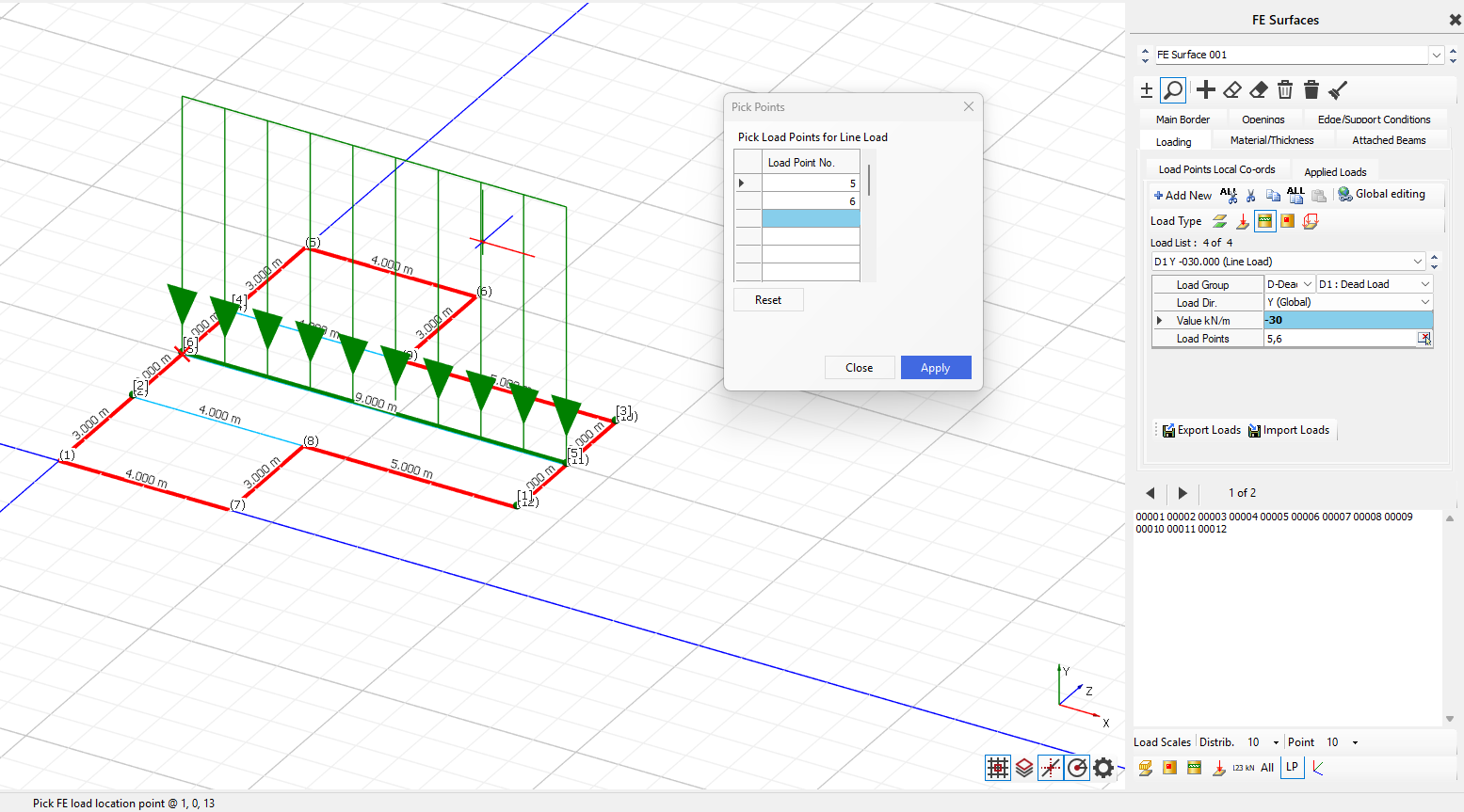
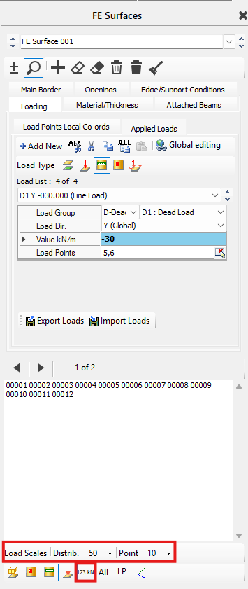
You can change the scale, view all the line loads and show the value of the loading by clicking on the icons shown below.
We are going to add more line loads by using the same procedure as before:
- Dead Load, -10.000, Nodes 6-19
- Dead Load, -10.000, Nodes 4-5
- Dead Load, -10.000, Nodes 1-2
- Dead Load- -10.000, Nodes 7-8
Now we will start to add Live Loads:
- Live Load, -5.000, Nodes 1-2
- Live Load, -5.000, Nodes 7-8
- Live Load, -5.000, Nodes 4-5
- Live Load, -5.000 Nodes 6-9
- Live Load, 10.000, Nodes 2-12
- Live Load, 10.000, Nodes 4-10
- Live Load- 20.000, Nodes 4-5
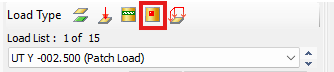
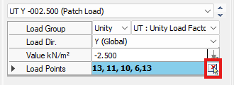
Patch Loads (Optional)
Patch Loads are accessed by going to Modify Geometry > Edit FE Surface and then clicking on the icon shown below.
To create a patch load, you first define the load values by inputting them onto the table. To select the area you want to create the patch load in, you click on the icon shown below and select the load points.
FE Loading Patterns
To insert FE Loading Patterns, go to Loads and then FE Surface Alternate Loading Patterns.

Pick Load set 1 and ensure that Auto Pick Alternative Panels is Selected. Select the panels so that you have alternating panels, the green represent the minor load cases.

Now select Load Set 2, ensure that Auto Pick Alternative Panels is selected. Select the panels shown below where pink represents max load cases.

Supports
Go to Restraints>Nodal Static supports.
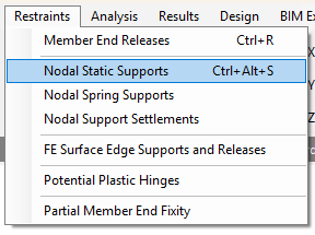
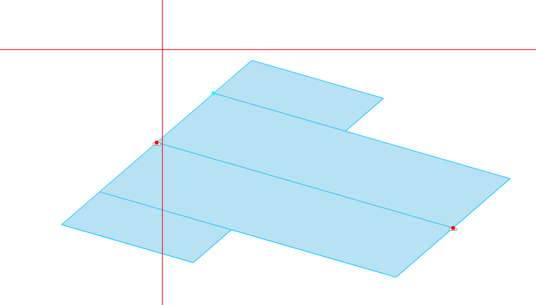
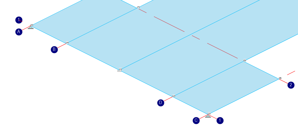
Click others, apply it to Node 11 and 3, this is to stop the panel rotating.
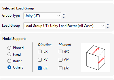
The using the the Add button we want to add a group for pinned supports, then select Nodes 1 and 5
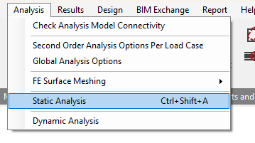
Analysing the frame
Go to Analysis> Static Analysis
Choose space frame analysis (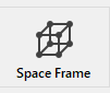 )
)
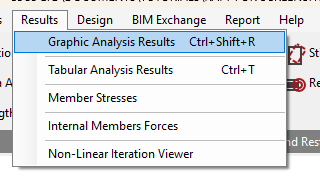
Next move to the Results menu and pick Graphic Analysis Results
Designing the slab
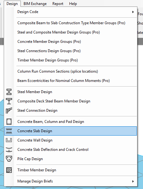
Go to Concrete Slab Design in the Design Tab.
on the pop up screen for Slab design basic data & defaults, click save and leave everything as the default value.
In the Slab reinforcement design start with the Basic ( ) type. Add new rebar set and apply it to the entire slab.
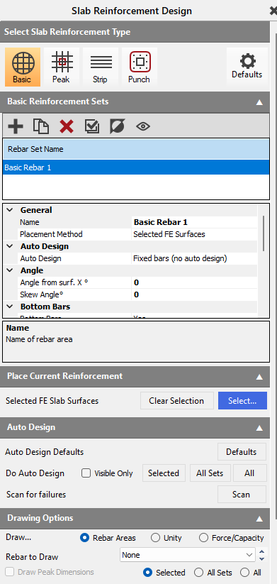
The Screen will turn up blue, this means the reinforcement isn't enough to support the slab. The Warnings in Red indicate what properties/sections are failing within the slab.
Now we need to consider the other options and find out what work best for our slab.
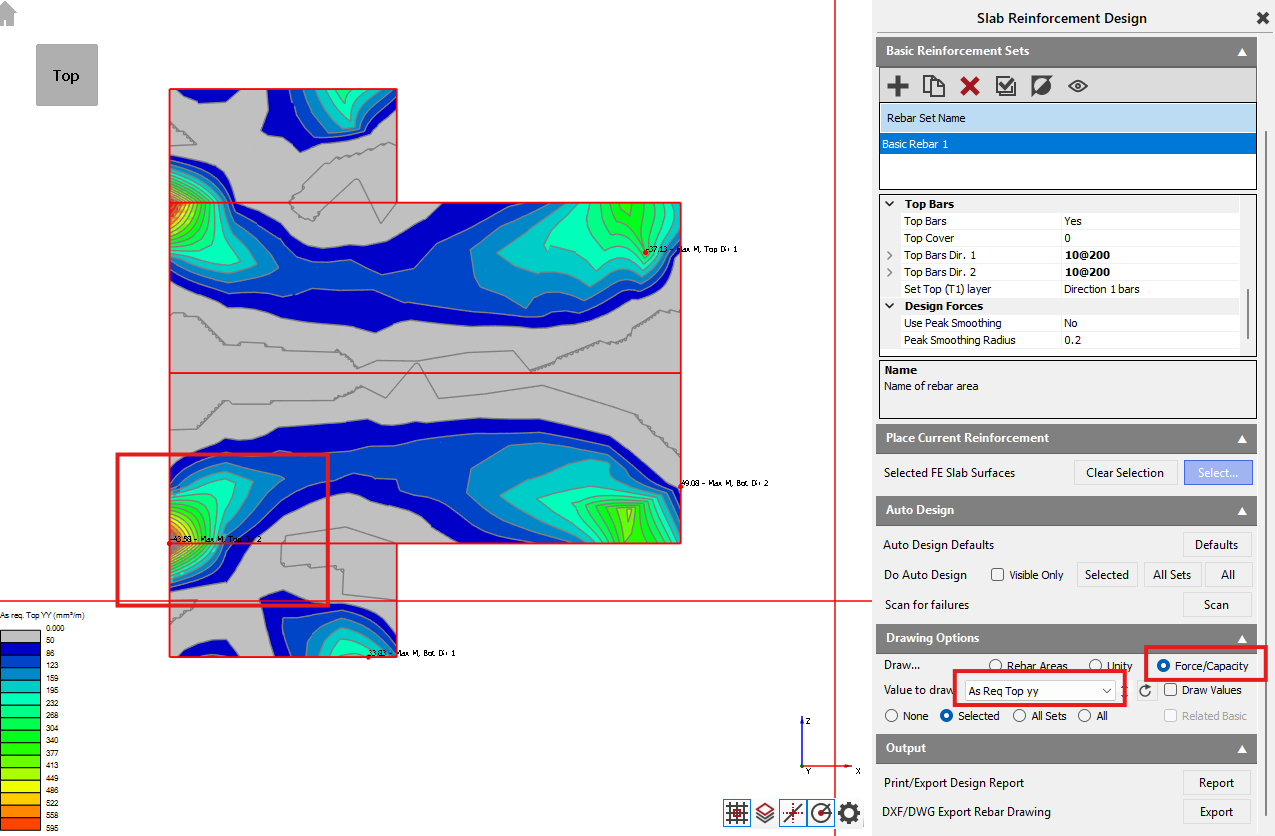
To get a further understanding of the slab we can click on the Force/capacity in the Drawing options section, then change the value to draw to AS Req Top yy.
this will show us the contours and the areas of most concern based on colour.
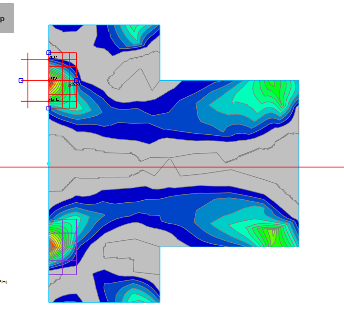
Now we are going to Add some Peak Reinforcement ( )
)
Click Add Multiple Mode( )
)
Then Select the Areas that are showing red dots as the are in need of support.
Set the design parameters for the peak zone in the properties panel. Configure options like:
- Whether the reinforcement adds to or replaces the basic reinforcement.
- The number of zones (single zone or split into middle/outer).
- The design force averaging method (e.g., average over full width, limited width, or limited by effective depth multiple). Averaging helps manage peak stresses for design.
- Reinforcement layout (bar size, spacing).
- Optional auto-sizing of the peak zone extent.
- Defining the parent FE surface if the peak zone crosses boundaries.
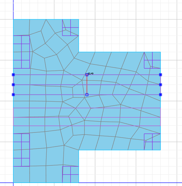
Next we are going to add the strip reinforcement ( ) Add to sections an equal distance from the mid line and reduce the width to 1m or 0.5 on each side.
Set the design parameters for the strip in the properties panel. Configure options like:
- Whether the reinforcement adds to or replaces the basic reinforcement.
- Reinforcement orientation relative to the strip line (perpendicular or parallel).
- The strip width, which is user-controlled.
- The design force averaging method (e.g., max value, limit width, effective depth multiple, or full width). Averaging is done perpendicular to the reinforcement direction.
Once this is done we have now set up all the elements, some properties need to be changed to ensure a fully functioning slab.
Properties
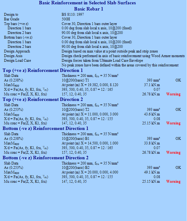
For the Basic Reinforcement change the Bottom Bars in Dir.2 to 10@150 and make sure the red warning had disappeared. Next move too Strip Reinforcement>Bars and change the bar diameter to 10 and the spacing to 400 to maximise space.
Once the Basic Reinforcement in Selected Slab Surfaces is White and all reads OK the Slab is complete.
Punching Shear Checks
Under
Slab Reinforcement Type, select 'Punching Shear'.
Add punching shear checks at required locations, typically by selecting the nodes at column tops or wall ends bearing on the slab. You can add multiple checks at once by pressing Add Multiple Mode.
Define the column or
wall dimensions if they are not modelled explicitly or if you need to adjust
the punching perimeter, then Press scan(  )and it will scan for failures
Review the punching shear checks. If checks fail even with drops, increasing the slab thickness may be necessary.
End of Tutorial