Global Member And Node Referencing
The Global Member and node Referencing allows the creation of member stamps and node Ids which are used to label the members and nodes in a Masterframe model. The Global Referencing labels are applied to any member of a model and do not change. This means that the Global Member Reference is a unique identifier. This is different from the member numbers and node numbers, which can be changed when the software carries out a relabelling are doing an frame renumbering. Thus, if a model geometry is modified, this can lead to a change in the member numbers (as well as to the node numbers) but the member reference is retained.
The Global Member Referencing menu
The Global Member Reference can be customised to include descriptors such as material, orientation, grid references, level, user-defined text, and a reference number. A single reference type can be used for all members, or different systems can be defined for beams, columns and bracing. Member references can be numbered sequentially across a level or on a level-by-level basis.
An option is also available to apply the Global Member Reference numbering to all Masterseries model output.
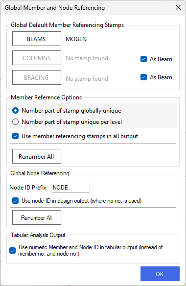
On selecting the Global member and node Referencing option from the Viewing drop down, the following pop up appears.
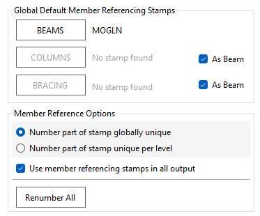
The default setting for the member reference is as shown, with the beam label set and the columns and bracing to be labelled as per the beams, as indicated by both the columns and beams being greyed out as the 'As beams' option ticked. The default set up also numbers the members uniquely over the whole of the model and will use the member reference in the outputs.
To set up the columns and beams to have independent labels, un-check the "As beams" tick boxes. Once done, the column and bracing icons will no longer be greyed out and can be selected by clicking on them with the mouse pointer.
Setting up a Member Reference label
The set up of the reference label is described for setting up on beams. However, the process is the same for columns and bracing members.
To access the set up menu for the beams, select the beams icon .png) . This opens the member stamp menu.
. This opens the member stamp menu.
.png)
The Top TAGS row lists the available tags while the STAMP row shows the current set up. Each tile in the STAMP row is selectable. the tiles can be dragged by selecting them and sing the mouse to move the tile. Thus tiles can be re-ordered by clicking and dragging. Tiles can also be removed from the STAMP line by dragging them into the TAGS row. Tiles can also be selected by hovering the mouse pointer over a tile and using the left mouse button to select and highlight the tile. When a tile is highlighted, a text description and options will appear in the right hand column of the Member Stamping menu.
The order of the tiles governs the order that the member information appears in the member reference stamp. By adding or removing tiles from the STAMP row, member information can be added or removed from the stamp.
The available tags are:
M - member material information
The Material information is shown below. In the right hand pane, the text descriptors are shown under the various heading. For example, if a member is Composite, the member reference with contain the letters Cp. Each line is customizable - selecting the text box, the text descriptor can be amended or deleted as required.
The trailing separator is simply a text separator. The default setting is to use a space.
O - Orientation
The orientation information is shown below. A text designator can be defined to denote beams, columns and bracing members. For a member to be identified as bracing, the relevant members need to be set as 'bracing' - see the area and wind loading menu items in the Loads chapter. Members which are vertical or close to vertical will be denoted as columns. All other members will be noted as beams. As per the member material descriptor, the trailing separator allows a user defined text separator to be defined.
G - Grid Lines
The Grid Line tag will incorporate the grid reference for members for any model which has grid lines set up. The separator determines the separator between the grid reference, the default separator is '\'. For example a column located on the intersection of grid line A and 5 will be noted as A\5. Again, a trailing separator can be set up to separate the grid references from the other reference text.
L - Levels
The Levels tag will include the level number as part of the member reference. Preceding text can be input. The default text is 'L', so the default setting will denote a beam at level 1 as 'L1'. Again the facility is provided to include a text separator.
T - Text
The text tag allows a text label to be included as part of the member reference. This text will apply to all member reference labels, which would mean that any text input here will appear on the member reference for all members in a frame.
# - Numbering
The numbering tag assigns a unique number to each member of the model. Each member is numbered sequentially throughout the model The number label can be unique over the whole model, or unique per level. This is controlled by selecting the "Number part of stamp globally unique" or "Number part of stamp unique per level" options from the Global Default Member Reference Stamps menu. The numbering used here is not he same as the member numbers. This is because all analytic members are assigned a member number, but not all analytic members are defined as physical members in a model. As an example, a member may be used to define part of the boundary of an FE surface. As such it is assigned a member number, but it is not a physical member and so does not received a member stamp.
Depending on the set up of the member referencing stamps, labels on members may not be unique. The "Only apply numbering to non-unique labels" allows a reference number to applied only in cases where other wise the stamp on a member is not unique. This can, in certain circumstances, reduce the length of the member reference label for members, since only some members will have an ID number.
Library
The Library feature allows a user to set up a member referencing system and to save this for use in other models. A descriptor or name can by typed into the input box at the top of the screen and then the referencing stamp saved. The library files are stored on each user PC.
Renumber All
In the Global Member Referencing menu, the Renumber All .png) function allows the number part of the member reference stamp to be updated. This can be done when the model has been amended in terms of frame geometry. This option will renumber all number tags in the whole model and so can potentially change every member stamp.
function allows the number part of the member reference stamp to be updated. This can be done when the model has been amended in terms of frame geometry. This option will renumber all number tags in the whole model and so can potentially change every member stamp.
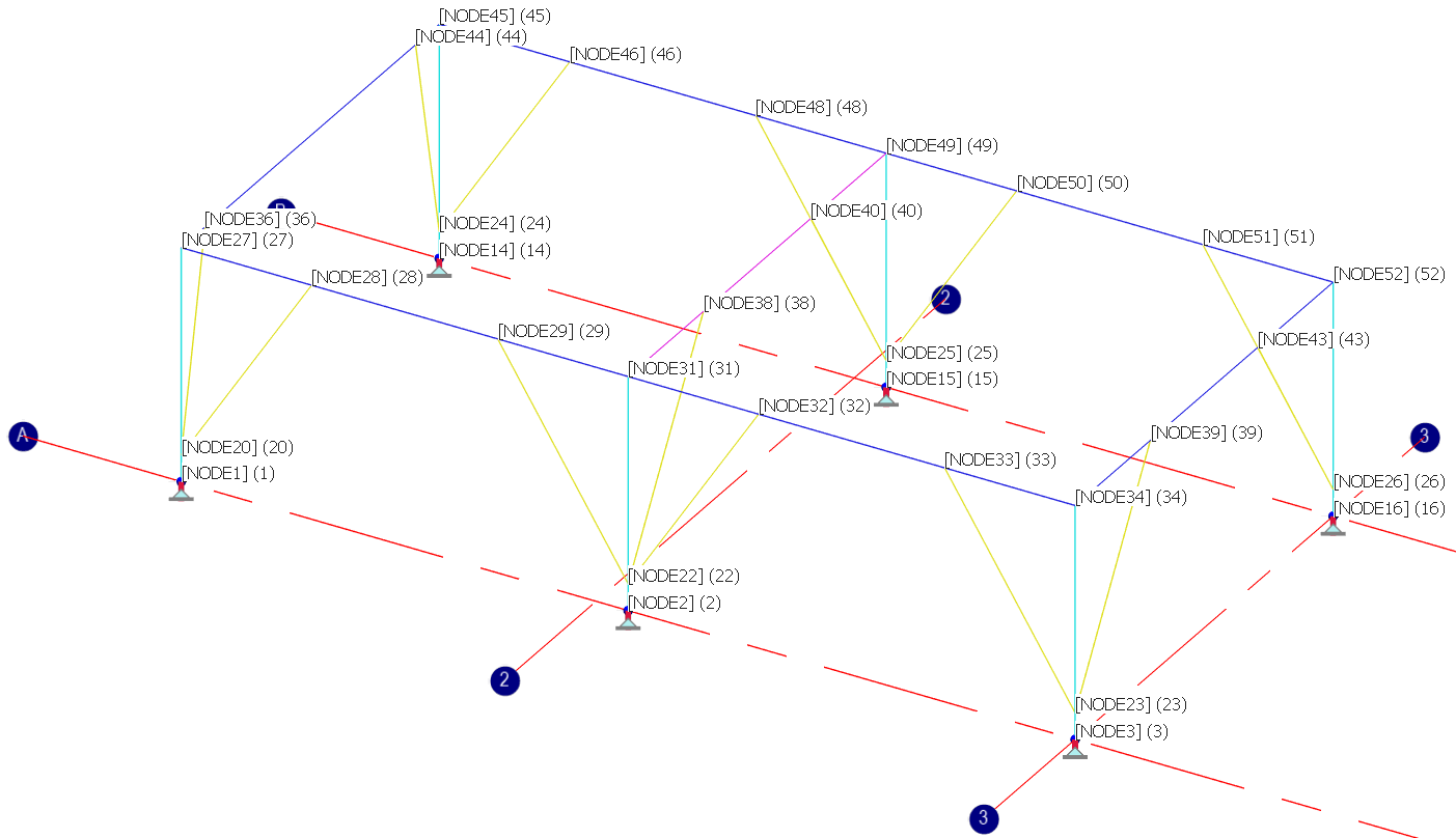
Global Node Referencing
Global Node Referencing allows the user to define consistent Node IDs for all nodes in the model. These references remain fixed and are not affected when new nodes are created through adding members or when existing members are modified. This approach ensures clarity and consistency when reviewing analysis and design results, as node identifiers remain unchanged throughout the design process.
An option is also provided to ensure that all related model output uses the Global Node Reference numbering, supporting a clear and consistent interpretation of results from start to finish.
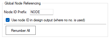
Node ID Prefix
This option allows the user to add a prefix to the Node IDs. In this example, where “Node” has been entered in the Node ID Prefix column, node references will appear in the format “Node XX”, where XX represents the unique node reference number.
Use Node ID in Design Output
If selected, Masterseries uses the node references instead of the internal node numbers in all design output. When displaying results, only the unique reference number (XX) is shown, without the prefix.
Renumber All
Renumber All function allows the Node ID reference stamp to be updated. This can be done when the model has been amended in terms of frame geometry. This option will renumber all number tags in the whole model and so can potentially change every Node stamp.
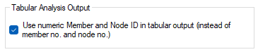
Tabular Analysis Output
This option allows the user to choose whether Member IDs and Node IDs are used in the tabular analysis output. When selected, the tabular analysis results display the Member IDs and Node IDs instead of the member and node numbers.