Creating Wind and Load Panels on Curved Dome Structures in MasterSeries
Guidance Note
When modeling structures with complex curved geometries, such as domes, for wind and area loading in MasterSeries, it's important to understand how the software defines "panels" and how this interacts with curved elements.
Key Considerations for Dome Structures:
- MasterSeries and Curved Members: MasterSeries is capable of designing physically curved members and performing full curved wind analysis on them, such as a barrel vaulted roof. These are typically defined as single members with underlying analytical segments.
- Panel Definition Requires Planar Surfaces: A critical rule for both wind panels and general area loading panels (load panels) in MasterSeries is that they must apply to a planar surface. While the software can handle curved members forming part of a panel's boundary (e.g., for a barrel vaulted roof where the plane is defined by the straight members along the length and the curved members form the end arches), a true dome, by its multi-directional curvature, does not present as a single planar surface.
- Automatic generation of External Pressure Coefficients (Cpe) will not be accurate: The Panel Generation within the software recognises vaulted roofs only (see BS EN 1991-1-4:2005 Figure 7.11 - Recommended values of external pressure coefficients Cpe.10 for vaulted roofs with rectangular base). Domes (Figure 7.12), differs from these typical classifications.
Recommended Approach for Dome Wind/Load Panels:
Approximate Curved Surfaces with Planar Facets (using Dummy Members):
- Since a dome is a multi-directionally curved surface, you cannot define it as one continuous panel. Instead, you will need to discretize the curved surface into many smaller, flat, planar facets.
- For areas where physical members do not exist to form these planar boundaries (e.g., between matching curved intermediate nodes), you should introduce "dummy members".
- Dummy members are non-structural elements that are ignored in the structural analysis but are crucial for defining the edges of area-loaded or wind-loaded panels. Loads applied to dummy members are transmitted to the nodes at their ends, ensuring no load is lost. This is a common solution for closing open-sided panels or defining edges where no physical member is present.
- Tip: Right Click within the Model Panel to Add a Dummy Member directly within the Panel Generation model space
- Ensure all perimeter members of each facet (including any dummy members) lie perfectly within a single plane for the panel to be created successfully.
Bracing Members:
- Always ensure that bracing members are correctly designated as such before creating wind or area loading panels. Bracing members are not directly loaded by area or wind loading, and if they are part of a panel's perimeter, the program will prevent the panel from forming or distribute loads incorrectly. You can set this attribute in the Member Property Editor.
Connectivity Checks:
- Hidden connectivity issues can prevent panels from forming. Use the Modify Geometry > Check and Modify Analytical Model > Model Auto Connect and Clean Up function to automatically connect members at their intersections.
Manual Overriding of Coefficients (Cpe):
- For a dome, the automatic generation of External Pressure Coefficients (Cpe) will not be accurate because the software's automated calculations are typically based on standard building shapes (e.g., rectangular plans, general sloping roofs). A dome deviates significantly from these standard classifications.
- Therefore, you must manually enter your own Cpe values in the 'Load/Cpe' tab for each defined planar facet. MasterSeries provides the flexibility to override automatically calculated values. This also applies to internal pressure and suction coefficients if they need specific adjustments beyond the defaults.
- See BS EN 1991-1-4:2005 Figure 7.12 - Recommended values of external pressure coefficients Cpe,10 for domes with circular base
- Alternatives
- Manually create Member Loading on the curved members, using Partially Distributed Loads in MasterFrame.
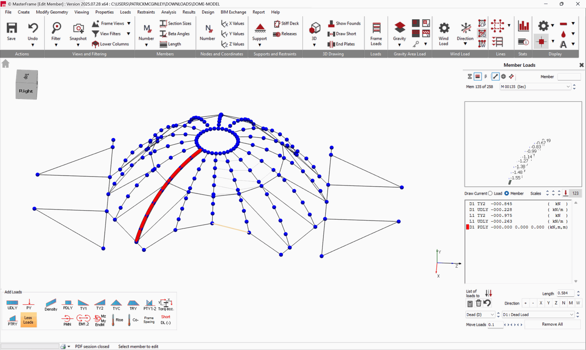

By carefully defining your dome as a series of planar facets using actual and dummy members, and then manually inputting the appropriate wind coefficients, you can accurately model the wind and area loading on your structure.