Modelling Slabs with Varying Thicknesses
When faced with a main slab with thinner sub-panels, traditional simplified modeling techniques may lead to an unrealistic analysis. Our technical experience indicates that special attention must be paid to the physical offset between these varying slab depths.
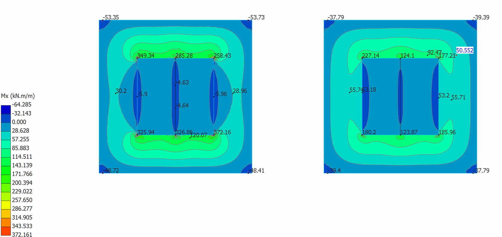
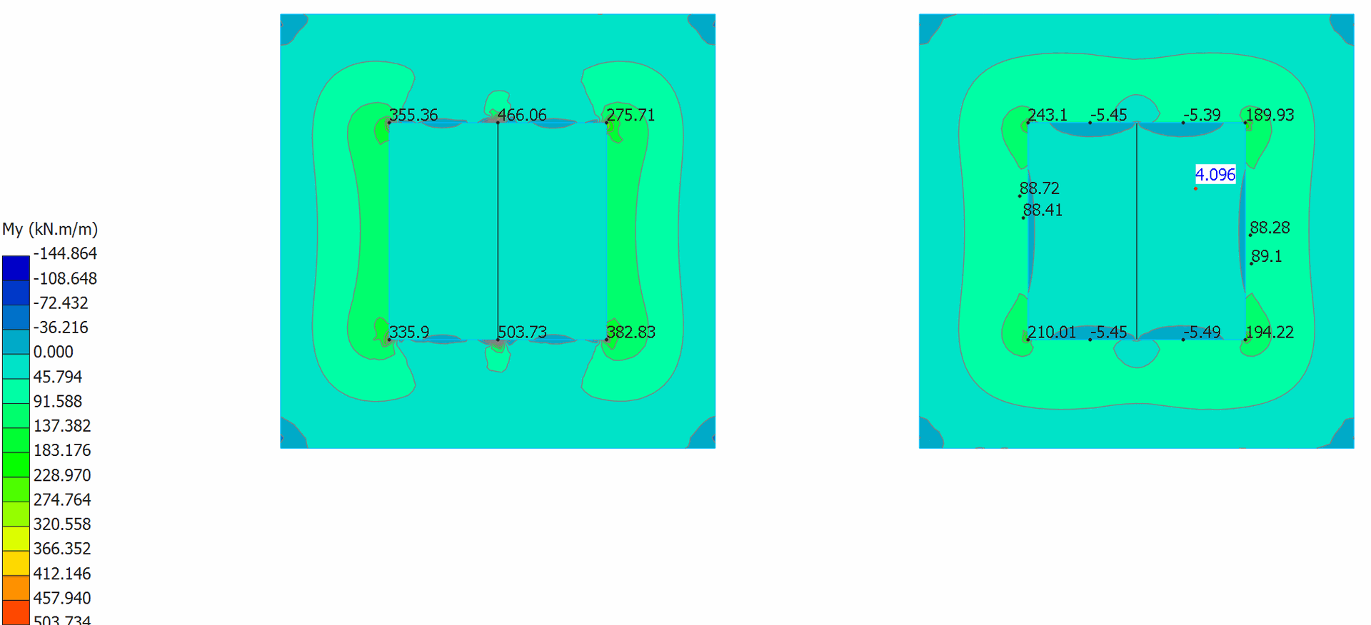
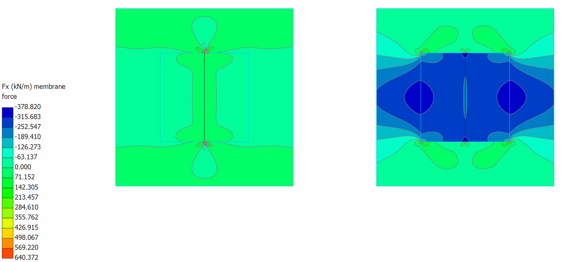
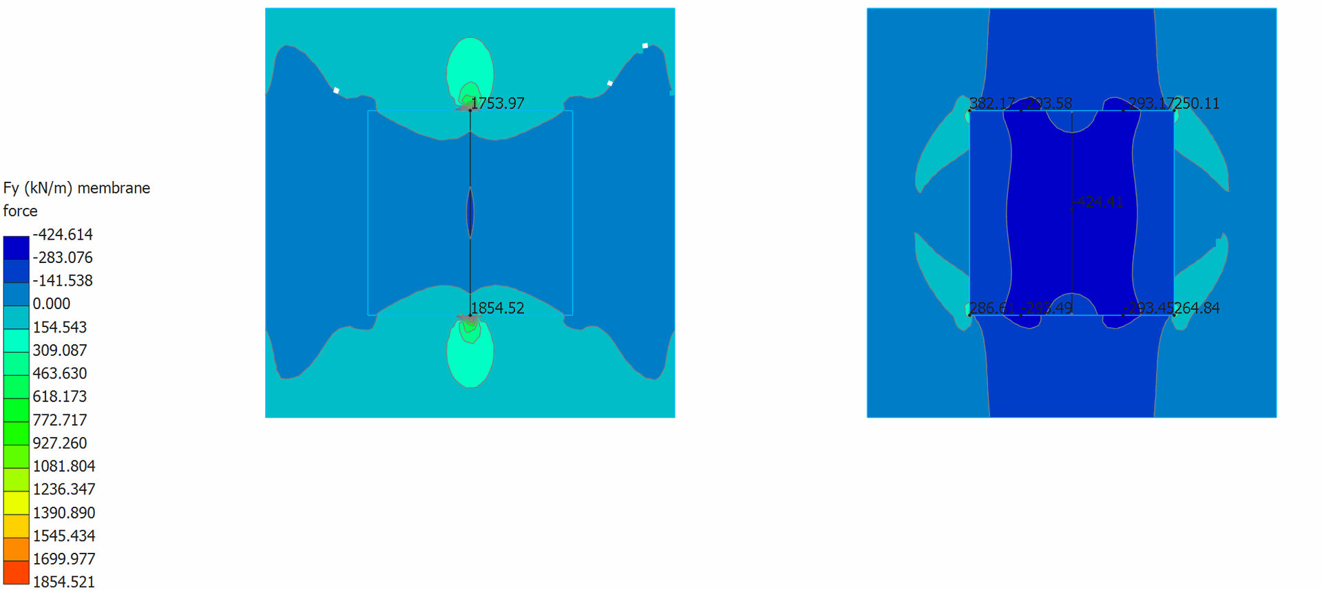
Modelling Thicker and Thinner Slabs as FE Surfaces on the Same Plane: While using FE surfaces is the correct approach for slabs, simply aligning the centre planes of the thicker and thinner slab portions has significant drawbacks. This method neglects the considerable vertical offset between the actual physical mid-planes of the slabs. Our recent slab offset modeling experiments demonstrate that this omission leads to notable discrepancies, such as an increased compression force in the thinner slab and altered distributions of Mx and My moments when the offset is correctly modeled. The FE module models planar surfaces based on the centreline of the element.

Recommended Modelling Approach:
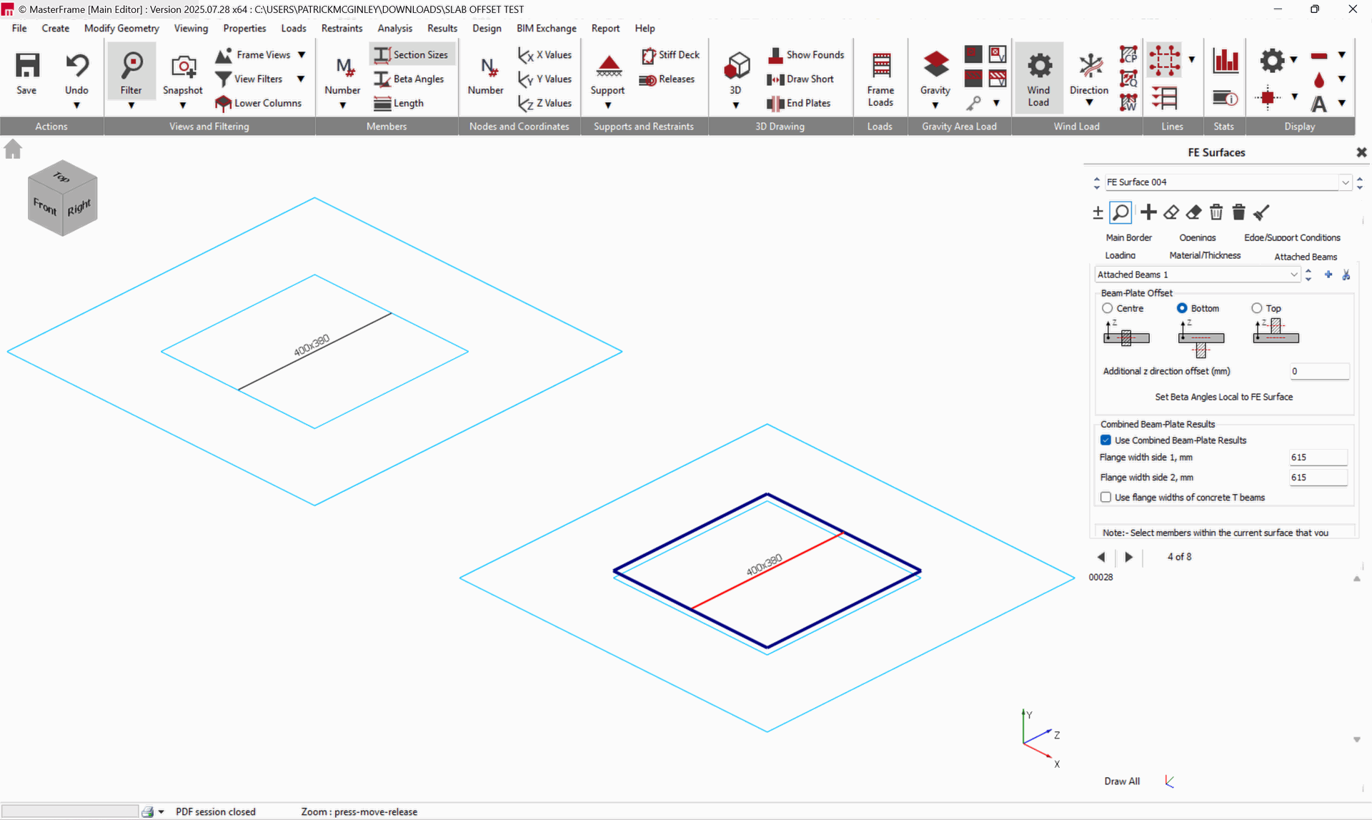
To achieve a realistic and accurate analysis in the following example (of a 10x10m slab simply supported with 5x5 thinner region with one bottom justified attached beam), we recommend the following methodology:
- Model Slabs at Correct Physical Centre Planes: Define the main 500mm thick slab and the 120mm thick sub-panels as separate FE surfaces, each placed at its true physical centreline elevation. This directly accounts for the vertical offset between the different thickness elements. You can set the thickness and material for each FE surface via the Material/Thickness tab.
Connect with 'Rigid' Vertical Surfaces: To seamlessly transfer forces between the offset slab portions, connect them using "rigid" vertical FE surfaces.
- Material Properties: These connecting surfaces should be defined with a density set to 0 to ensure they do not contribute to the self-weight of the structure. To achieve rigidity, assign a very high Young's Modulus (E-value) to the material for these elements, ensuring they are stiff enough to transfer all forces in a rigid manner, meaning they experience negligible deformation.
- Thickness: Typically, these rigid vertical surfaces should have the same thickness as the thicker slab (e.g., 500mm in your case).
- Function: Their primary objective is to act as a rigid link, effectively transferring all forces and moments between the different slab levels without significant internal deformation.

- Meshing Considerations: When implementing this approach, pay close attention to the FE mesh. MasterSeries' FE module requires compatibility between adjacent FE surfaces, ensuring that nodes coincide along common boundaries and elements share common edges. Thin elements, or elements in close proximity, can sometimes lead to meshing challenges. If meshing issues arise, consult the "Diagnosing common issues with FE meshing" technical note for strategies such as using internal dummy members to subdivide regions or adjusting mesh density.
- Result Verification: After analysis, thoroughly review the graphical analysis results, specifically focusing on bending moments (Mx, My) and shear forces. Confirm that the force distribution and stress patterns are logical and reflect the intended rigid connections and the effect of the slab offset, as demonstrated by our internal experiments (e.g., observing increased compression forces in thinner offset regions). Hand calculations for simplified sections can also provide a valuable check for the overall magnitude of results.
By following this refined modelling strategy, you can achieve a more accurate and representative analysis of slabs with significant thickness variations in MasterSeries, leading to more reliable design outcomes.