MasterFrame Pro - Shear Wall Modeling
Technical Note
Title: Shear
Wall Modelling in MasterFrame
Date: 16/10/2003
Versions: 2002.05+
Program: MasterFrame
The effects of shear walls can be included in MasterFrame,
primarily for the purposes of assessing the frame lateral stability. The shear walls can be included in the
MasterFrame model by generating vertical centre line elements of each
wall.
The proposed method also models
the torsional stiffness of the core based on the summation of the torsional
stiffness of the individual shear walls.
This assessment is accurate where the shear core forms an open section
such as a ‘C’ shape. However, for a closed shear core section, such as a box
shape, the torsional stiffness will be under estimated.
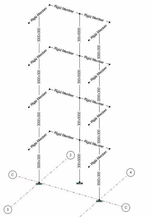
Example:
![]()

The structure shown above has a three sided ‘C’ shaped shear
core. The sections of the structure,
shown below, represent the arrangement of members necessary to model the shear
stiffness of the core.
![]() Vertical members are
located at the centre of each shear wall.
The dimension of the member is equal to the thickness and width of the
wall.
Vertical members are
located at the centre of each shear wall.
The dimension of the member is equal to the thickness and width of the
wall.
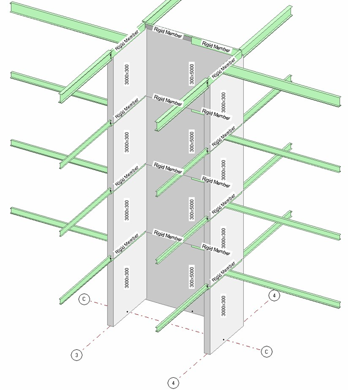
To enable the transfer of forces from the structure to the
shear walls, rigid horizontal members are modelled around the perimeter of the
shear core. These rigid members should
be given user section properties with very large Ix and Iy second moments of
area. These members are also
instrumental in representing the combined effect of the shear core system. The rigid link members may also have the 'UT (Rigid Link Member)' member attribute applied, however this has the sole purpose of identify the member as a non-physical member, such that their self weight is automatically ignored, they is not drawn in 3D and are excluded from any BIM operations. The 'UT (Rigid Link Member)' does not affect the member stiffness is any way. The engineer is advised to examine the deflected shape of the model to ensure excessive bending is not observed in the link members relative to the deflection of the shear wall column members.
It is also advisable to fix the
bases of the vertical shear wall members.
Note that with the ‘stiff-deck’ effect activated on the
floors, all horizontal forces will be transferred automatically to shear core.
Important ! With this method it is essential that the
‘Cases>Torsional Stiffness> Include Shear Deflection’ option is
checked.
Ignoring the effects of shear deflection would be dangerous,
leading to unrealistically increased lateral stiffness of the structure.
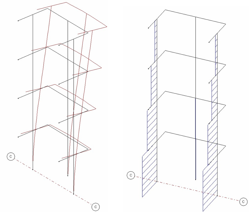
Deflect Shape Shear
Force