MasterFrame Pro - Setting up a Mixed Composite/Non-Composite Floor
Technical Note
Title: Setting up a Mixed Composite/Non-Composite Floor
Date: 30/05/2011
Versions: 2011.05+
Program: MasterFrame 3D Model Manager & Composite Beam Design
Introduction
When creating a structure which has a mixture of composite and non-composite areas, a particular floor or roof may need to be split between a composite area and a non-composite area. For example, a roof may have steel beams with an insulated cladding finish. Over a part of the roof, there may be a plant room, the floor of which is to be of composite construction. This mixed area can be set up within the 3D Model Manager as follows:-
Method
The areas of the program which are involved in setting up the mixed floor are the Area Loading Defaults, Mixed Construction (Composite and Non-Composite) and Gravity Area, Line and Patch Loading, all of which are found under the ‘3D Model’ menu.
The composite beams must be released in the major axes so that they are simply supported. Also primary beams formed from several members must be set up as supermembers.
In ‘3D Model’ > ‘Gravity Area, Line and Patch Loading’ > ‘Area Loading Defaults’ – on the ‘Area Loading’ tab, set the mixed construction floor level to non-composite (N) in the Composite/Non-Composite data line.
In
‘3D Model’ > ‘Member
Groups’ > ‘Mixed Construction
(Composite and Non-Composite)’ – select all the composite members in the floor (highlighted in red), then alter the ‘Change Non/Composite’ option to Composite.
Add in the Default Loads for the composite area.

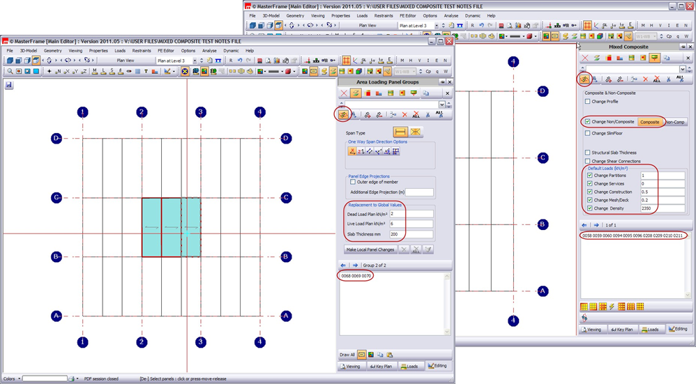
In ‘3D Model’ > ‘Gravity Area Line and Patch Loading’ >
‘Area Loading Panel Groups’ – the panels must be entered with their loading and slab thickness, if these differ from the default values for that level.
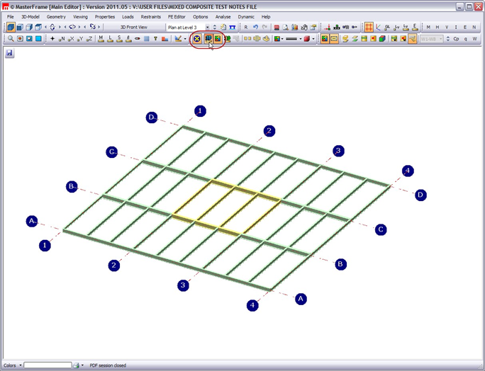
Checking the beams are composite action
Switch on the blue 3D button – members coloured yellow are considered as composite floor beams, green coloured members are considered as steel (but non-composite) and blue coloured members are considered to be bracing (or members not directly loaded by gravity or wind loads).
Hence you can see at a glance if the frame is set up the way you want.
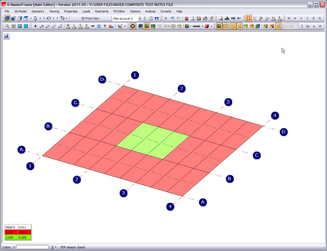
Checking the area loading is right
Switch on the area loading and legend to view the loaded areas and check their intensities.
Regards