T02-3 3D Multi-bay Portal frame

Introduction
This tutorial will require you to have access to MasterPort Plus.
If you do not have access to any of this software, please contact us for a 14-day free trial to learn how it can benefit you and your business.
Overview & Outcome
In this tutorial, we will aim to create a portal frame using MasterPort Plus with the aim of providing you with a solid understanding of:
- Generating a 3D portal frame
- Applying loads to the frame
- Viewing frame loadings
- Analysis and the results
- Design of steel members
Version Information
This tutorial has been written for version 2024 of the MasterSeries software suite. Subsequent versions of the software may have additional features or changes in layout, however the general procedure will remain the same.
Contact
We strive to make our tutorials as simple as possible without compromising on the technical aspects of the analysis procedure. Should you discover any errors, omissions, or are in need of additional clarification, please contact us by emailing your comments, or corrections to help@masterseries.com
We’re social – follow us on Facebook ,LinkedIn Vimeo and to keep up to date!
Loading MasterPort
To start this tutorial, launch the main program of MasterSeries.
While standing on the Programs tab, select the MasterPort from the Integrated Analysis & Design filed

Hovering over the MasterPort icon, the available integrated design options appear with small icons.
The File Selector dialogue
The File Selector dialogue will now be displayed.
You can use the File Selector to navigate in your folder tree and to select, modify or delete your existing model files or create a new one.

 ) button on the top of the file selector tree, we can see the saved
favourite folders. By selecting one of them, the file tree will immediately jump to there. By clicking the
Star icon at the end of the line, we can remove or add each of them.
The table, on the right of the File Selector (#3), lists all of the MasterFrame models contained in
the selected folder.
) button on the top of the file selector tree, we can see the saved
favourite folders. By selecting one of them, the file tree will immediately jump to there. By clicking the
Star icon at the end of the line, we can remove or add each of them.
The table, on the right of the File Selector (#3), lists all of the MasterFrame models contained in
the selected folder.The Simplified MasterPort Interface
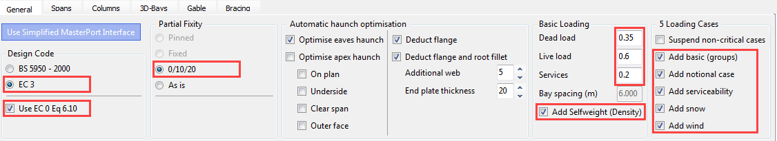
On the General tab, we can find all of the analysis and design related functionalities.
Set the following options:
- Ensure that the Design Code is set to EC 3 and check-in Use EC 0 Eq 6.10 option
- Select 0/10/20 as the partial base fixity for the portal columns
- In the Basic Loading field, type 0.35, 0.6 and 0.2 for Dead, Live and Services plan loads respectively and ensure that Add Selfweight (Density) is checked
- Select Add basic (groups), Add notional case, Add serviceability, Add snow and Add wind to automatically create the relevant ultimate and service load cases
- Accept the default for the haunch optimisation
The Spans Tab – Rafter Information
On the Spans tab, we can set the details and properties of the rafters and additional features like lean-tos and cranes.
Select the Spans tab and set the following settings:
- Click on the spans dropdown list and increase the number of spans to 2
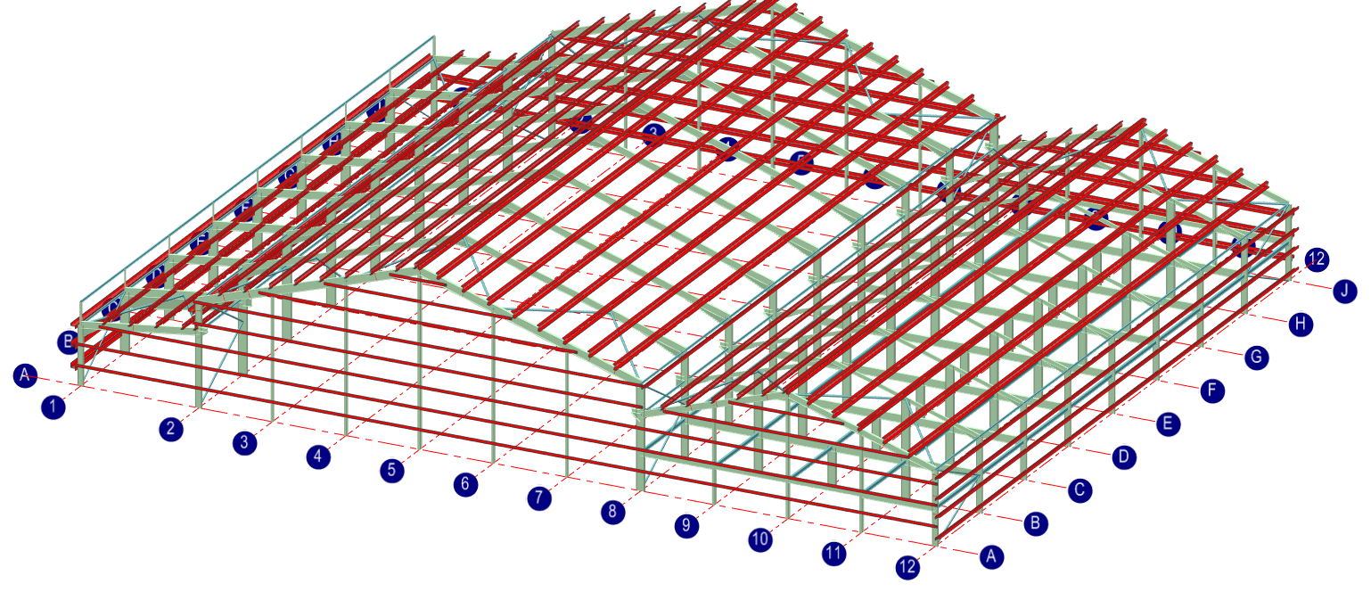
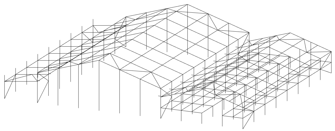
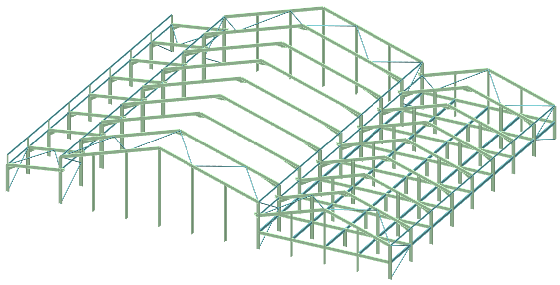
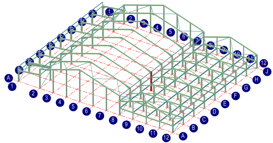
- Click on the Generate 3D Frame (
 ) button to display a 3D frame instead of a plane frame
 - Turn off the Global Symmetry (
 ) option
 - Turn on the Propped Portal (
 ) option
 - Turn on the Lean-tos (
 ) option
 - Turn on the Cranes (
 ) option
 - Turn on the Mezzanine (
 ) option
The number of portal spans has
been increased to two. With the Global
Symmetry (
) option off you can make the two spans different from one
another.
Using the table input, change the L (m) length of the Span 2 to 20 m. and then set the Lh1 eaves haunch length for the Span 2 to 2 m.
Set the Rafter Section & Grade for Span 1 by highlighting the cell and clicking the button that appears. Accept the default section of 457 x 191 UB 67 and change the grade to S 275.
Repeat this for Span 2.
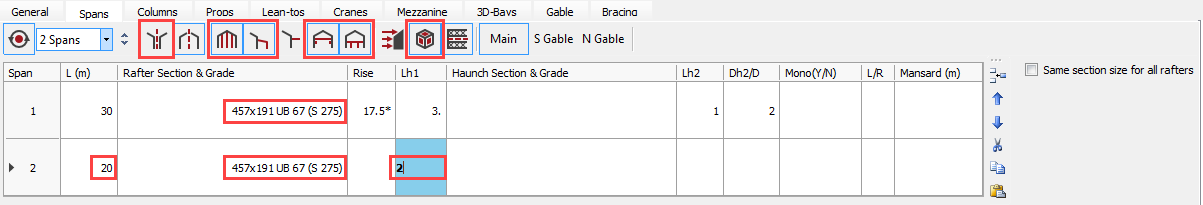
Leaving the Haunch Section & Grade cell blank will ensure the haunch assume the same section size as the rafter.
The Columns Tab – Main Portal Columns
The Columns tab will give you access to input boxes relating to the main portal columns. Here you can alter the column heights, section sizes, base levels, fixities, and column parapet details.
Select the Columns tab and set the following settings:
- Type 7-2 in the Top Level (m) data cell for Column 2 to set different eave hight for the second span
- Type 5 in the Top Level (m) data cell for Column 3
- Select the Main button, if it is not selected, and click on the Section and Grade cell for Column 3 clicking the button that appears
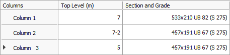
- Accept the default 457 x 191 UB 67 section and change the grade to S 275
- Change the grade of Column 2 and Column 1 to S 275, leaving the section sizes as they are
By entering individual section sizes for all three main columns, each of them will be designed separately giving a particular section size for each longitudinal line of columns.
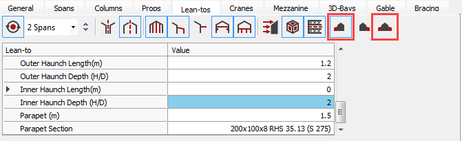
The Lean-tos Tab – Main Portal Columns
Select the Lean-tos tab and using the table input set the following settings:
- Click the Symmetrical
Lean-to on Both Sides (
 ) button off
 - Type 0 for the Inner Fixity %
This will give a pinned end connection to the lean-to rafter where it connects to the min portal column. Leaving the Outer Fixity % blank defaults this value to 100% (rigid connection to lean-to column)
- Type 1.2 for the Outer Haunch Length (m) and 0 for the Inner Haunch Length (m)
You have now set up a lean-to on one side of the structure.
The Cranes Tab – Adding Crane Loading
Select the Cranes tab.
This tab gives you access to the input table related to cranes. The program evaluates the maximum and minimum horizontal and vertical loads applied to the frame by the crane, based on typical manufacturer’s data.
The default date is for a 20-tonne crane within Span 1. The default values will suffice for this tutorial.
The Props and Mezzanine Tabs – Adding a Mezzanine Floor
At first, select the Props tab and set the following settings:
- Under Span No. replace the 1 with a 2 to move the props from the Span 1 to the Span 2.
- Type a Y under Release Top (Y/N) in the first line. This will cause the top of the prop column to be pinned.
- By default, the props will stop under the mezzanine floor. Typing N in the Top @ Mezz (Y/N) would cause the prop to carry on up to the underside of the rafter.
The section size and grade can be altered if required, but this is not necessary as the section will be automatically sized later.
Move to the Mezzanine tab.
This will give you access to the input boxes relating to the mezzanine floor. You can alter the floor height, loadings, the floor section size, and beam end fixities.
Set the following settings:
- Delete the height for Span 1 under the MezH heading – no floor will appear in Span 1
- Type 2.5 for Span 2 to create a mezzanine floor in the second span at a height of 2.5 meters
You can now alter the section size and grade if required, although this is not necessary.
Note the Dead, Serv and Live floor loadings for the floor. The default values will suffice for this tutorial.
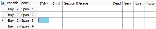
The mezzanine floor is split across the span with there being no floor in Span 3 of Bay 2.
Delete N from the Bay 2 – Span 3 row so that the floor will cross the whole of Bay 2.
The Bay Spacing and Main Gable Frames
Click on the 3D-Bays tab.
In the Bay Spacing data area, the portal bays have been set up as 8 bay spacing of 6 meters each. The specific portal frame which will be considered in the design is frame 3.
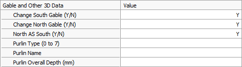
The end frames in a portal can be full portals, half portals or gables frames. Here we will design the end frames as half portals, both ends being identical:
· Type Y in the Change South Gable (Y/N)
· Repeat the above for both Change North Gable (Y/N) and North AS South (Y/N)
Select the Spans tab and click on the Gable button.
- Click on the South Gable Section & Grade cell for Span 1 and click on the button that appears
- Select an initial section size of 457 x191 UB 82, grade S275
- Repeat this for Span 2
Defining the section sizes for the gable corner columns and rafters separately from the main portal section sizes will force these members to be designed independently of the main portals.
If left blank the section size will default to that of the main portal.
The Bay Spacing and Main Gable Frames
Click on the Gable tab.
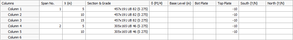
The first three gable column positions are set by default to 5, 10 and 15 meters in the Span 1.
To set the gable columns for the Span 2:
- Type 2 under Span No. in Column 4
- Type 5 under X(m) in line Column 4
- Type 10 under X(m) in line Column 5
This will put gable columns in the second portal span and mirror them about its centre line thus placing the third column on the RHS.
- Click under the Section & Grade for Column 1 and click on the button that appears
- Select an initial section size of 457 x 191 UB 82, grade S 275
- Repeat this for Column 2 and 3
- Select a 305 x 165 UB 46, grade S275 for Column 4 and 5 in Span 2
Gable end columns are often designed to take the wind loads in bending but not to carry any axial loads from the rafter. This is usually carried out in practice by using a vertically slotted connection at the top of the column.
This situation can be easily set up in MasterPort by putting a negative value in the thickness of the top plate.
· Type -10 under Top Plate for each column
The Bracing and Longitudinal Ties
Click on the Bracing tab.
The program will automatically set up longitudinal tie members along the length of the frame at the usual tie positions. In this case at eaves level and the mezzanine floor level.
Default section sizes are also specified. These defaults and section sizes can be altered if required. A longitudinal tie member will be added at the top of the parapet.
The Y shown in the Main Spans line under T(Y/N) indicates that there are longitudinal transfer members along with the roof connection the bracing systems at each end. These transfer members allow the bracing at both ends of the structure to share the wind loads, and so the bracing section sizes will be more realistic in size. These members will only be used in the analysis i.e. they won’t be used in design. In this tutorial transfer members will be omitted.
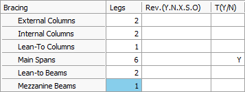
Click on the cell containing the Y and delete it. The transfer members will be removed.
Switching off the Use Detailed Bracing Members List ( ) button will give access to the list of tie and bracing
members. Individual tie or bracing members can now be modified if necessary. By
clicking on a particular tie or bracing member, the relevant data cell will be
accessed in the table and modification can be made.
) button will give access to the list of tie and bracing
members. Individual tie or bracing members can now be modified if necessary. By
clicking on a particular tie or bracing member, the relevant data cell will be
accessed in the table and modification can be made.
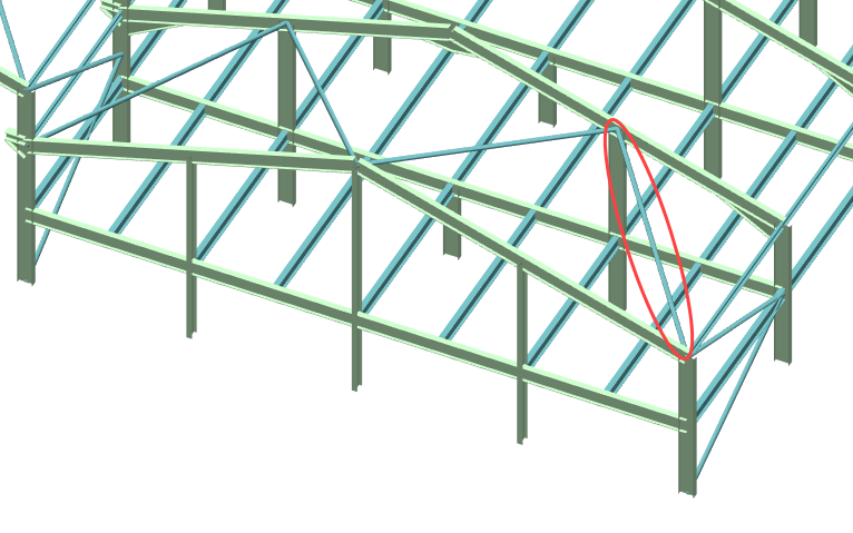
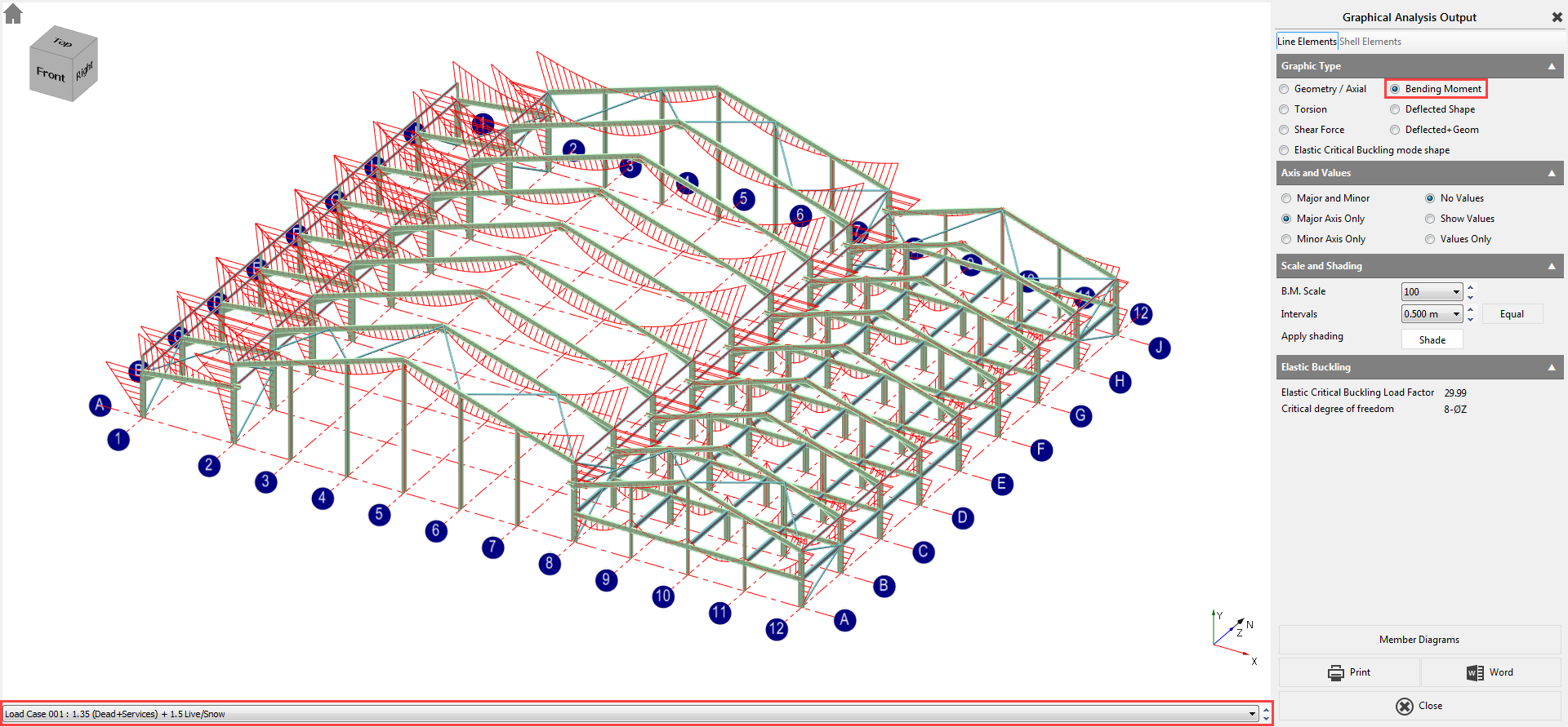
We will adjust the Span 2 roof baring to props:
- Select the outside roof bracing member on the lower portal frame roof
- The corresponding Brace 22 data cell in the table will now have the cursor in it
- On line Brace 22 under X2 replace the current dimension with 5
The end position of the bracing member moves further up the slope of the second rafter.
- On line Brace 23 under X1, replace the current dimension with 10, and replace X2 with 5
The second bracing member moves, starting at 10 meters along the first rafter and finishing at 5 meters along the second rafter.
- Click on the start of the line for Brace 24 to highlight it and click on
the Cut (
 ) button at the end of the line to delete this line the
bracing member it represents is no longer required
) button at the end of the line to delete this line the
bracing member it represents is no longer required
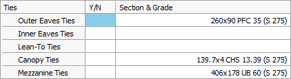
You can add a longitudinal tie along the top of the parapet up stands on the lean-to part of the structure.
- On line Brace 30 under Bay No. type 1-
- Under Span No. type 0, and then type W in the next column
- Under X1 and X2 type 5.5
- Under Section & Grade click in the cell to bring up the grey button
- Click the grey button to display the sections database, and select a 260 x 90 PFC, grade S275 as the longitudinal tie member
Defining the Wind and Snow Loads
Activate the Wind/Snow tabs by
clicking on the Apply Wind/Snow Load on
Portal Frame (
 ) button.
Wind loading
Click on the Wind tab.
We can set manually the wind pressures in the different directions or, by clicking on the Use MasterKey Wind q values option, we can use the inbuilt MasterKey: Wind Analysis module to automatically define the proper wind pressure values based on the location.
Check in the Use MasterKey Wind q values option.
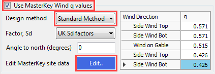
From the Design method drop list select the Standard Method and click on the Edit… button to set the site location.
MasterKey Wind Analysis module will be opened in a new window.
Site location can be selected by using
- the maps to pick the a location followed by the
 button to update, or
 - using the one of the Type and Value search methods in the Site Data tab.
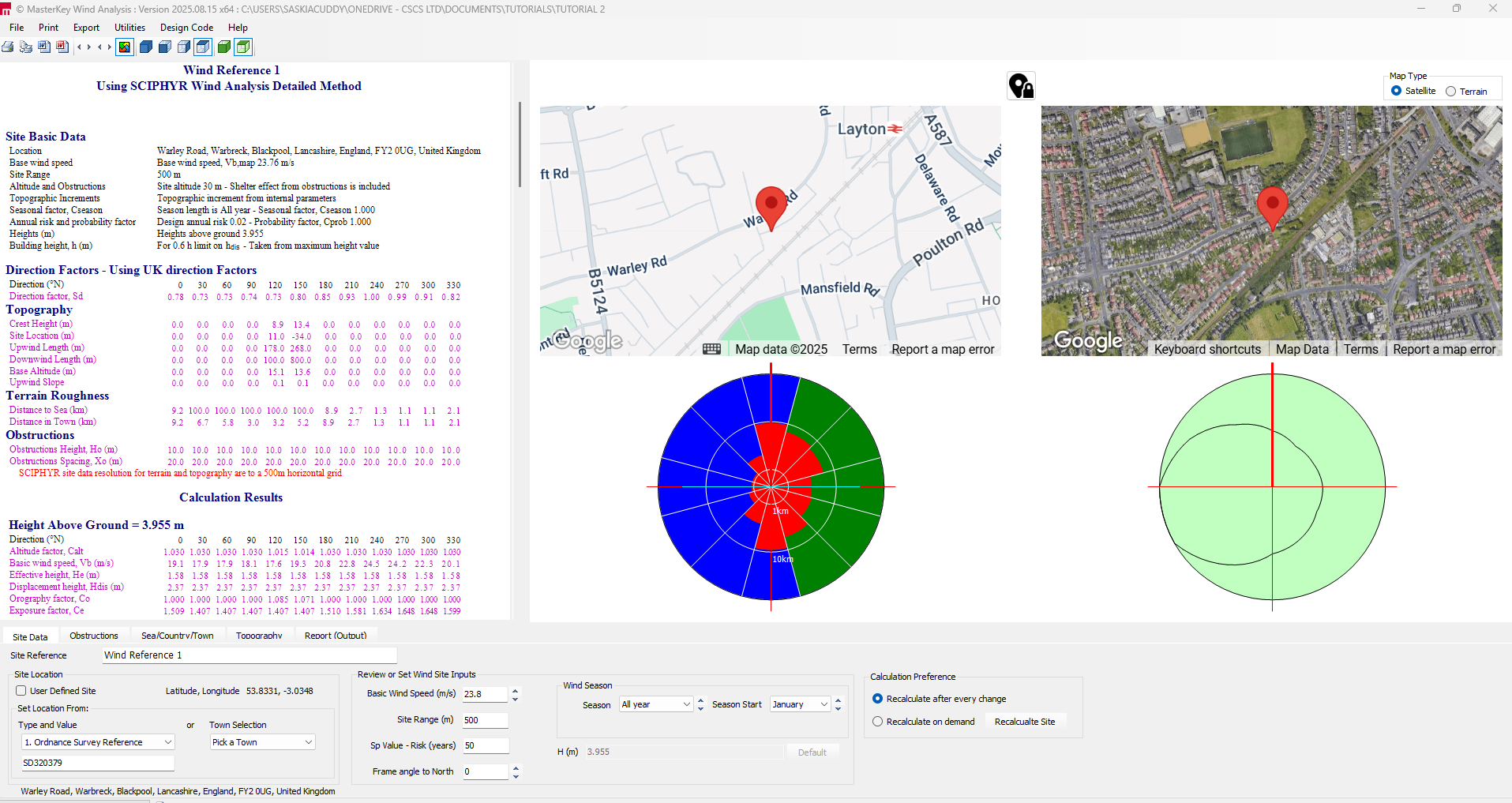
From the file menu, select File and Exit MasterKey Wind.
The wind pressure values are automatically updated in the table.
Additional wind load cases are generated to include internal pressure (Cpi) giving the P group of wind cases and internal suction (Csi) giving the S group of wind cases. Therefore there are three sets of wind load cases developed. Note that there is no need to place a “-“ sign in front of the suction coefficient.
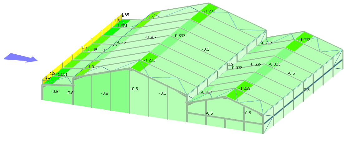
Turn on the Wind ( ) button from the top toolbar’s Wind Load group to display the wind
loading.
) button from the top toolbar’s Wind Load group to display the wind
loading.
Using the Direction (
 ) function you can examine the wind in each direction. Using
the wind loading visualisation options
) function you can examine the wind in each direction. Using
the wind loading visualisation options you can see the generated wind coefficients, pressures and
zones on each surface.
you can see the generated wind coefficients, pressures and
zones on each surface.
Snow loading
Click on the Snow tab and set the followings:
- Type 0.6 in the Z zone number NA.1 value box
- Type 120 for the Site Altitude (m)
The program will use these values to evaluate the symmetrical and asymmetrical snow loads including drifting against parapets, walls, and in valleys in accordance with the selected standard.
Select the Snow Load (
 ) button in the Portal
group to see a graphical representation of the snow load.
) button in the Portal
group to see a graphical representation of the snow load.
You can scroll through the different load cases (L0 – L5) and see the different snow distributions using the dropdown list to the right of the Snow Load button.
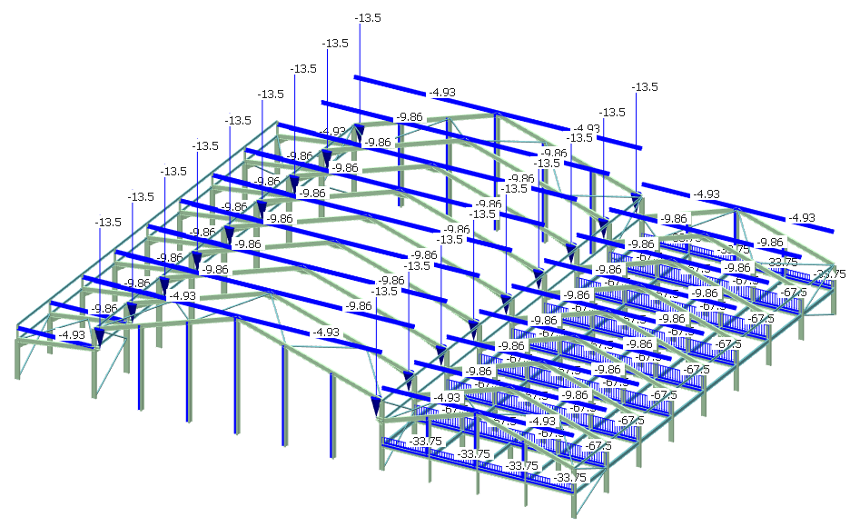
Viewing Frame Loadings
To view the frame loadings according to their load cases and load
groups, click on the Frame Loads
( ) on the top toolbar.
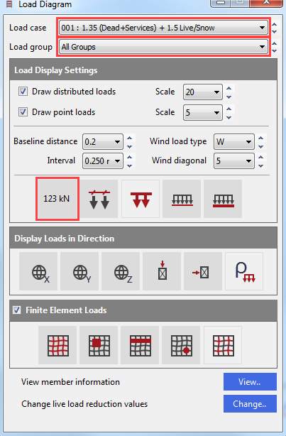
The Load Diagram dialogue appeared.
Click on the Display Values (
 ) button to show the loading values.
Click on the Load cases droplist to view the different load cases. The factored loads in the selected load case will be displayed on the frame.
Click on the Load groups to select and view a particular loading group. The unfactored loads in the selected loading group will be displayed on the frame.
Close the dialogue using the X button.
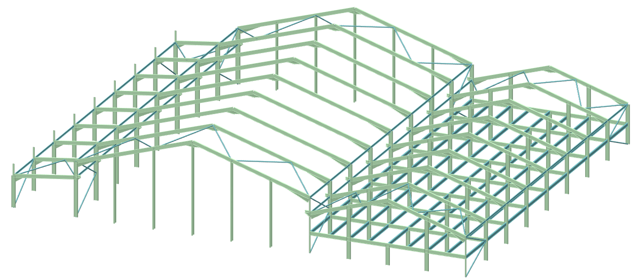
Viewing Options
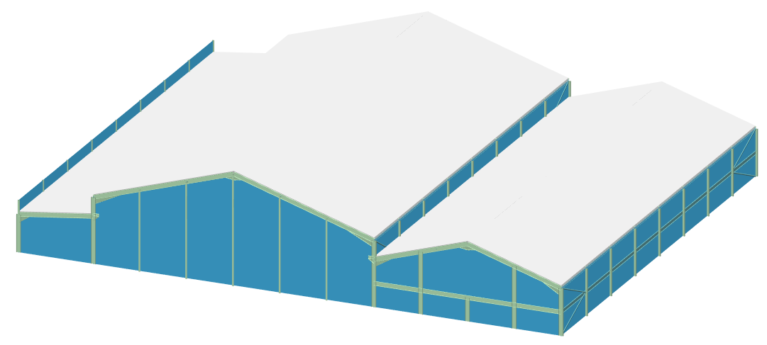
To see the 3D view of the
structure click on the 3D
(
) button in the 3D Drawing
group of the top toolbar.
button in the 3D Drawing
group of the top toolbar.
To display the automatically
generated structural grids, click on the Grids
(
 ) button in the Grid Lines
and Levels groups.
) button in the Grid Lines
and Levels groups.
Click on the Draw Purlins ( ) button in the Portals
group to display the layout of the purlins and side rails.
) button in the Portals
group to display the layout of the purlins and side rails.

Analysis and Results
For the sake of time, the number of load cases in this tutorial will be reduced.
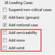
Go to the General tab and remove the ticks from the boxes for Add wind, Add snow and Add serviceability.
This will leave the dead and live load cases combined with notional and crane loadings but will omit those involving wind and snow loads. If you wish, you may analyse all 168 load cases and carry on through to steel design.
From the top menu click on the Analyse option and select the Plastic Analysis. Click OK to proceed.
The Analysis Results
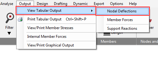
To see the analysis result, got to Output and View Tabular Output and then select for example Nodal Deflections.
The options in the lower part of the screen enable you to control the results being displayed and are very easy to use. When there is a large amount of data the vertical scroll bar controls the view.
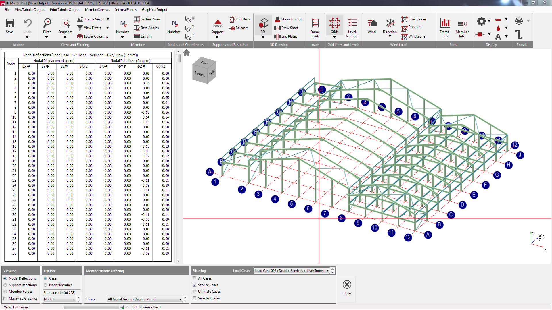
The standard method of viewing results is List per Case. This only display results in one loading case at a time. The other method is to List per Node/Member. This is useful to compare results for different loading cases for the same node or member as shown here.
Navigate between the three options on the bottom of the Tabular Output screen to view the results.
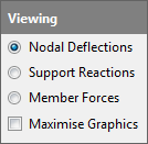
To view the results in graphical format, click on the Graphical Output from the main menu.
Select the Bending Moment diagram option. We have no members bending about the minor axis so select Major Axis Only on the right-hand panel. Select Show Values.
Using the dropdown list at the bottom of the graphical display, you will be able to scroll between the different load cases including the envelopes.
Click on the Close button to return to the main menu.
Steel Design
From the Design menu, select Steel Design.
Each part of the overall structure will be examined as a group so that you can retrain engineering control over your design.
The Main Portal Frame Design
Click on the Main Portal Members ( ) button at the bottom of the graphical display.
The Automatic Design defaults are set to Size as a Plastic Portal using the Lightest section that passes the design check and to opt for partial fixity 0/10/20 at the column bases.
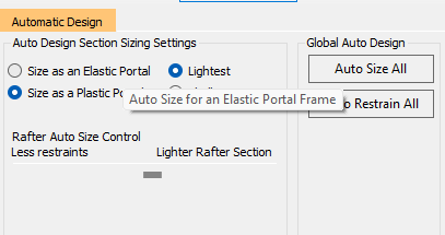
You also have control over whether you want the automatic design to give the lightest rafter possible at the expense of more restraints or to reduce the number of restraints needed by using a slightly heavier section. Leaving the slider in the middle will give a reasonable balance between the weight and the number of restraints required.
Click on the Auto Size All ( ) to begin the automatic design process for the members in the
frame.
) to begin the automatic design process for the members in the
frame.
Next, click on the Auto Restrain All ( ) button to automatically optimise the restraints.
The program initially spaces the cladding rails at 1.4-meter centres and purlins at 1.8-meter centres and reduces the spacing if required.
On the columns, the first rail will be placed at the bottom of the haunch and then spaced from this point down.
Torsional restraints will be placed where needed at rail and purlin positions to satisfy the requirements of Appendix BB in Eurocode 3.
To see the calculations for
each member designed, click on the Portal Frame
Final Design Stage, Purlins, Side Rails and Torsional Restraints button  .
.
This will access the design check for each set of members in the frame, allowing you to see exactly where a member has failed.
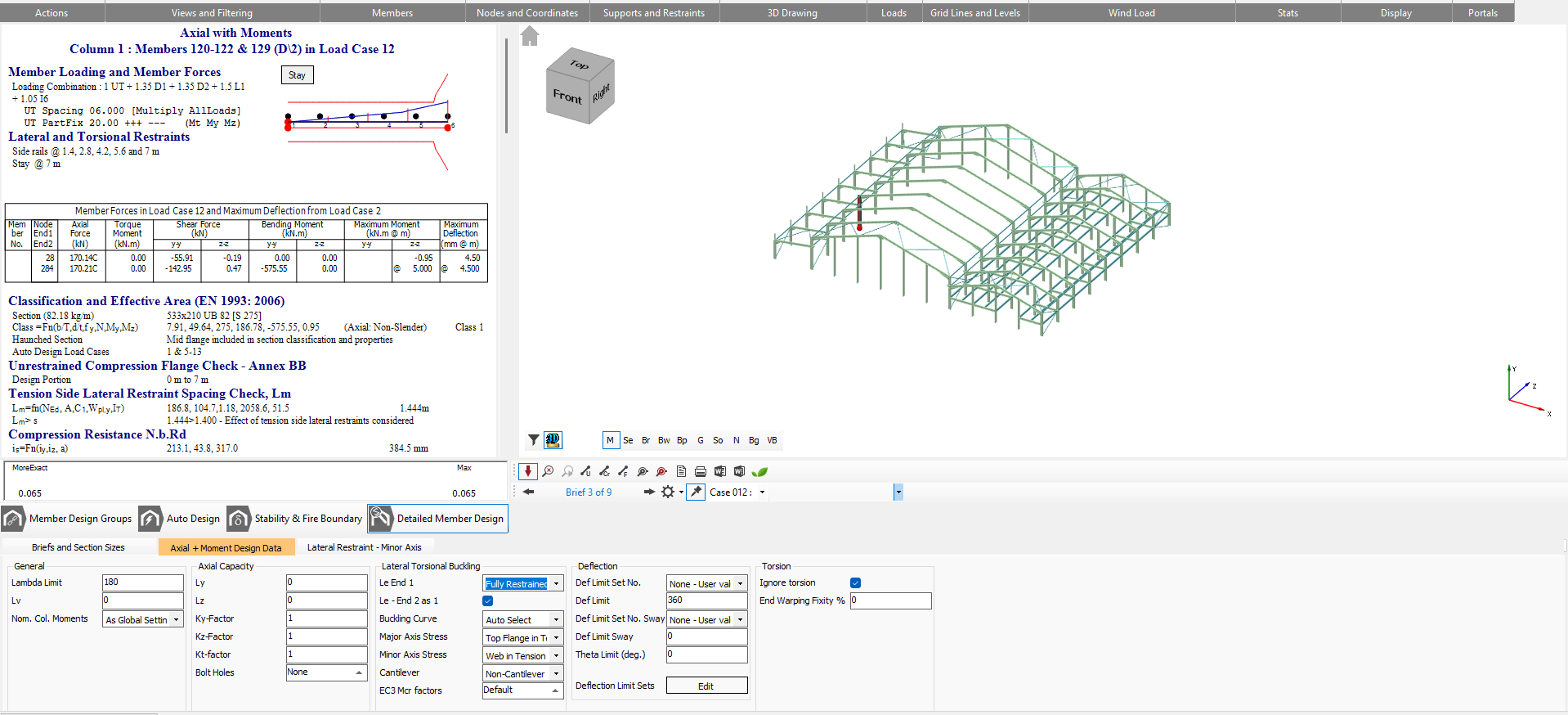
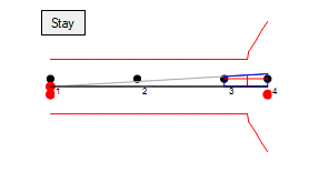
In the Lateral Restraints tab, the portion of the column being considered along with the critical load case relevant to that portion. The automatic spacing can also be viewed in the corresponding tables.
Clicking into each portion of the bending moment diagram at the top of the calculations section will display the calculations for the particular portion of the column.
Click on an internal column shared by both portal frames and click on the Lateral Restraints-MinorAxis tab.
As this is an internal column no lateral restraints will have been provided. However, they will likely be required at 5 and 7 meters respectively.
Type 5 into Portion 1 and 2 into Portion 2.
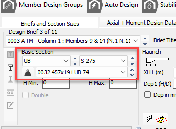
The section size can now be reduced to reflect the improved restraint conditions.
Go to the Briefs and Section Sizes tab, and reduce the section size to 457 x 191 UB 74.
In the Lateral Restraints-MinorAxis type 2 in the first row the of Lateral Restraint No. grid to specify a torsional stay at the bottom compression flange at purlin number 2. Addressing Failures
Using the Scan for failures function, the program will highlight the first member (if any) to have failed.
Click on the Scan for failures  button to see the failing members.
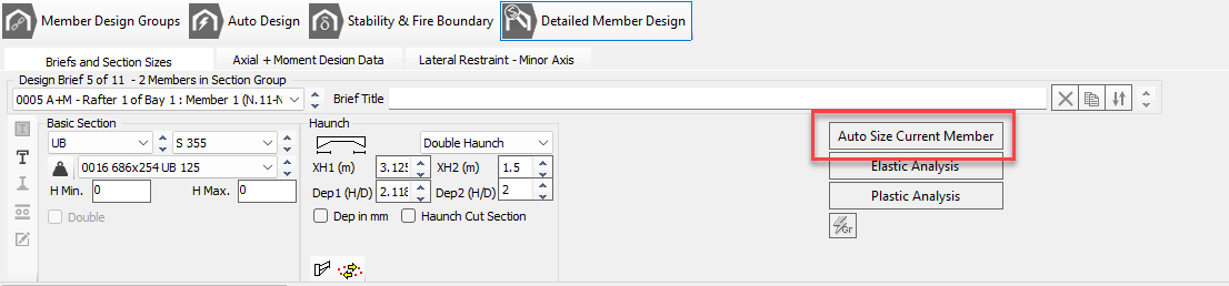
Using the scroll buttons to the side of the section size, move up through the section sizes until you find a suitable section that passes, or alternatively, you can click Auto Size Current Member button.
The detailed results dialogue will change from blue to white once the checks all pass.
Click the Move to next failure (
 ) button and continue to address the section sizes.Once all the items have been
addressed you will need to analyse the frame.
) button and continue to address the section sizes.Once all the items have been
addressed you will need to analyse the frame.
Click the Re-Analyse button and then click the Scan for failures (
 ) button to ensure the frame has passed all checks.
Design of Secondary Members
The secondary members comprise of the mezzanine floor main beams and beams, and the parapet members.
Click on the Secondary Members (
 ) button from the bottom of the graphical display.
Navigate to the Briefs and Section Sizes tab and click on the Auto size all members independently ( ) button.
The four floor members have been set up in the one section group. Therefore the group will have the same section size and will be designed for the most onerous load case found in the same four beams. Similarly, the three mezzanine columns are in one group and will be designed as the same section size.
Design of Roof Bracing Members
Click on the Roof Bracing Members ( ) button.
Click on the Auto size all members independently (
) button.
Design of Roof Bracing Members
The wall bracing members include the vertical diagonal bracing in the sidewalls and the longitudinal tie members at the wall/floor, and wall/roof interfaces, as well as the top of the parapet.
Click on the Wall Bracing Members ( ) button.
Click on the Auto size all members independently (
) button.
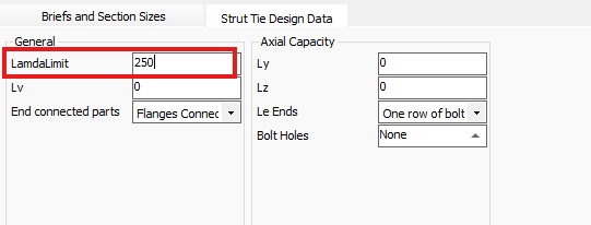
Select the Strut and Tie tab and overtype the 180 with a new Lambda Limit of 250.
Since there are 6 eaves members, the lambda limit should be altered for all 6.
Click on the Move to next brief button.
Alter the Lambda Limit to 250.
Continue to alter the limit for all failing briefs.
Once complete you may Scan for
failures (
).
Design of Internal Longitudinal Tie Members
Click on the Longitudinal Tie Members (
 ) button.
Click on the Auto size all members independently (
 ) button.
Design of Gable Columns Design
Click on the Gable Columns ( ) button
Click on the Auto size all members independently (
) button.
Design of Gable Columns Design
Since both gable frames were designated as being the same, this design will apply to both gable ends.
Click on the South Gable Frame (
 ) button.
Click on the Auto size all members independently (
) button.
Select the Lateral Restraints tab and click on the Auto Restrain Current Group button. This will restrain the portal leg for both cladding rails and torsional restraints.
Select each of the group members in turn and click on the Auto Restrain Current Group for each set.
Click the Scan for failures (
) button and address any issues with the design.
Printing The Design Output
You can print the calculations for each group of members, by selecting which individual checks you wish to print for each group using the options located below the frame graphics area.
Click on the Main Portal Members () button to go back to the design checks for the main frame.
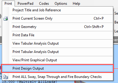
Select the Print Design Output option from the Print menu and select Include All.
The program will run through all the checks for all portions for this group of members and check whether each portion passes or fails. Rather than print all calculations for all portions of all members, you can optimise the print out by printing only the critical portion for each member.
Check the Critical Portion Only checkbox and click on the Auto Select button.
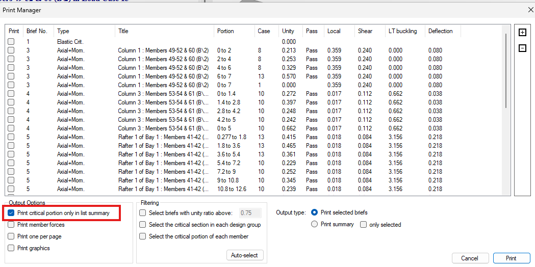
Only the critical portion for each member will be selected.
Selecting to Print List (Summary) will print the list as seen at the bottom of the screen with a single line for each check.
Selecting to Print Selected Checks will print out comprehensive calculations for each highlighted portion check.
Click on the Cancel button in this instance.
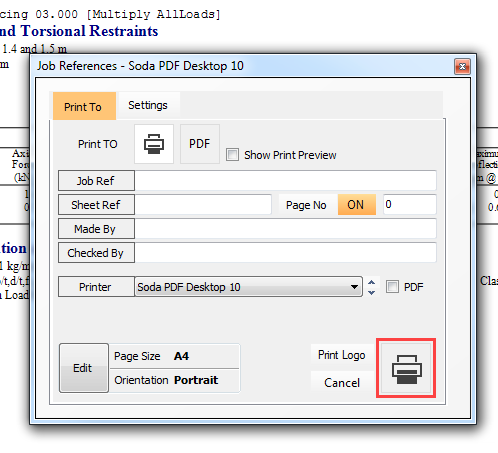
Now, select the Print Current Screen Only option from the Print menu.
Select the Print button in the Job References dialogue box and the brief for the current member will be printed.
End of Tutorial