T02-2 Three-Bays Portal Frame
Introduction
This tutorial will require you to have access to MasterPort Plus, MasterPort Lite or PowerPad.
If you do not have access to any of this software, please contact us for a 14-day free trial to learn how MasterSeries can benefit you and your business.
Overview & Outcome
In this tutorial, we will aim to create a portal frame using MasterPort with the aim of providing you with a solid understanding of:
- Generating a portal frame
- Applying loads to the frame
- Elastic-plastic analysis and the results
- Design of steel members
Version Information
This tutorial has been written for version 2024 of the MasterSeries software suite. Subsequent versions of the software may have additional features or changes in layout, however, the general procedure will remain the same.
Contact
We strive to make our tutorials as simple as possible without compromising on the technical aspects of the analysis procedure. Should you discover any errors, omissions, or are in need of additional clarification, please contact us by emailing your comments, or corrections to help@masterseries.com.
We’re social – follow us on Facebook, LinkedIn and Vimeo to keep up to date!
Loading MasterPort
To start this tutorial, launch the main program of MasterSeries.
While standing on the Programs tab, select the MasterPort from the Integrated Analysis & Design filed

Hovering over the MasterPort icon, the available integrated design options appear with small icons.
The File Selector dialogue
The File Selector dialogue will now be displayed. You can use the File Selector to navigate in your folder tree and to select, modify or delete your existing model files or create a new one.
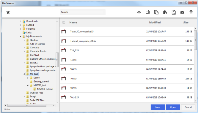
To create a new model file click on the New button on the bottom, then type the name (for example Tutor02-2) and click on the Create button.
The Simplified MasterPort Interface
Using the simplified MasterPort interface we can set up quickly the initial details of the portal frame. A standard single-span plane portal frame is automatically generated.
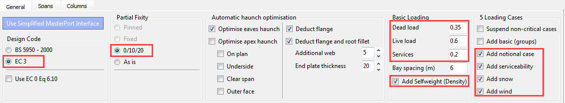
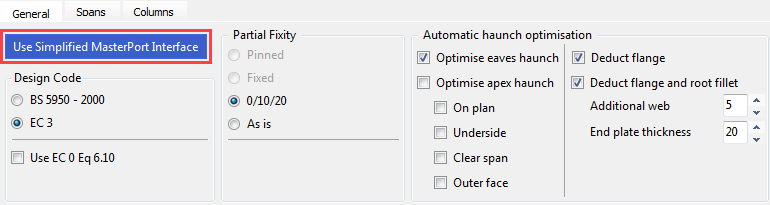
On the General tab, we can find all of the analysis and design related functionalities.
Set the following options:
- Ensure that the Design Code is set to EC 3 and check-in Use EC 0 Eq 6.10 option
- Select 0/10/20 as the partial base fixity for the portal columns
- In the Basic Loading field, type 0.35, 0.6 and 0.2 for Dead, Live and Services loads respectively and ensure that Add Selfweight (Density) is checked
- Select Add notional case, Add snow and Add wind to automatically create the relevant ultimate and service load cases
- Accept the default for the haunch optimisation
The Spans Tab – Rafter Information
On the Spans tab, we can set the details and properties of the rafters and additional features like lean-tos and cranes.
Place the frame in front view
by selecting the Front side of
the viewing cube ( ).
).
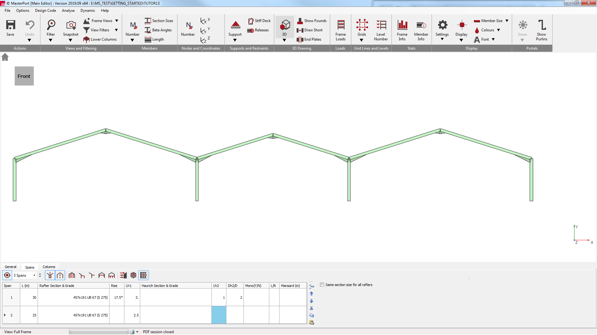
Select the Spans tab and set the following settings:
- Click on the spans dropdown list and increase the number of spans to 3 Spans.
- The number of portal spans will be increased to 3. With the Global Symmetry option selected, the outer spans (Span 1 and Span 3) will have the same span length.
- For Span 2, change the Length (L) of the span to 25 m by highlighting the cell and inserting the value
- Click in the Rafter Section & Grade cell to set the section size of Span 2. Accept the default 457 x 191 UB 67. Change the grade to S275 if it is necessary
- Ensure that the rafter section and grade for Span 1 (and Span 3) are the same section and grade
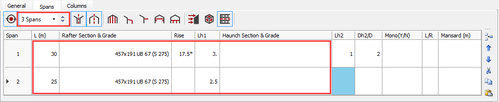
By leaving the Rise cell blank for Span 2, the value of 17.5 degrees from the above cell will be applied by default.
- Set Lh1 to 3 m for Span 1 and for Span 2 to change the haunch length to 2.5 meters
Leaving the Haunch Section & Grade cell blank will ensure the haunch assume the same section size as the rafter.
The Columns Tab – Main Portal Columns
The Columns tab will give you access to input boxes relating to the main portal columns. Here you can alter the column heights, section sizes, base levels, fixities, and column parapet details.
Select the Columns tab and set the following settings:
- Type 7 in the Top Level (m) cell for Column 1 to set the column height to 7 meters
This makes the height of the first column 7 meters. Subsequent cells will be defaulted to the value of the first.
- Click in the Section & Grade cell for Column 1. Click on the grey button that appears at the end of the cell to access the Steel Sections database.
- Change the grade to S275 and accept the default section size of 457 x 191 UB 67. Click on the Close button to apply the changes
- Change the grade of Column 2 to S275 and keep the default section
By entering individual section sizes for the outer and inner columns, each set of columns will be designed separately and thus can be optimised during the design process. If the Section & Grade cell is blank, it will always assume the section of the cell above.

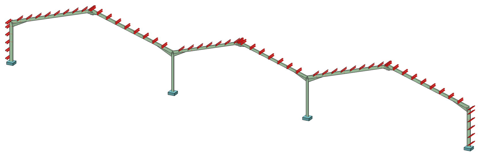
Defining the Wind Loads and Load Combinations
At this point the structure is basically set read to analyse, however, we want to add some wind loading. These additions are outside of the scape of the simplified editing facilities. The data entered so far will be saved and you can continue to edit the frame further.
Switch off the Simplified MasterPort Interface button in the General tab.
Wind Loading
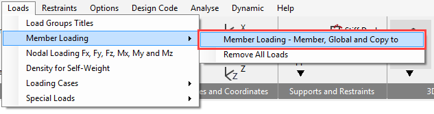
From the Loads and than Member Loading menu, select Member Loading – Member, Global and Copy to option.
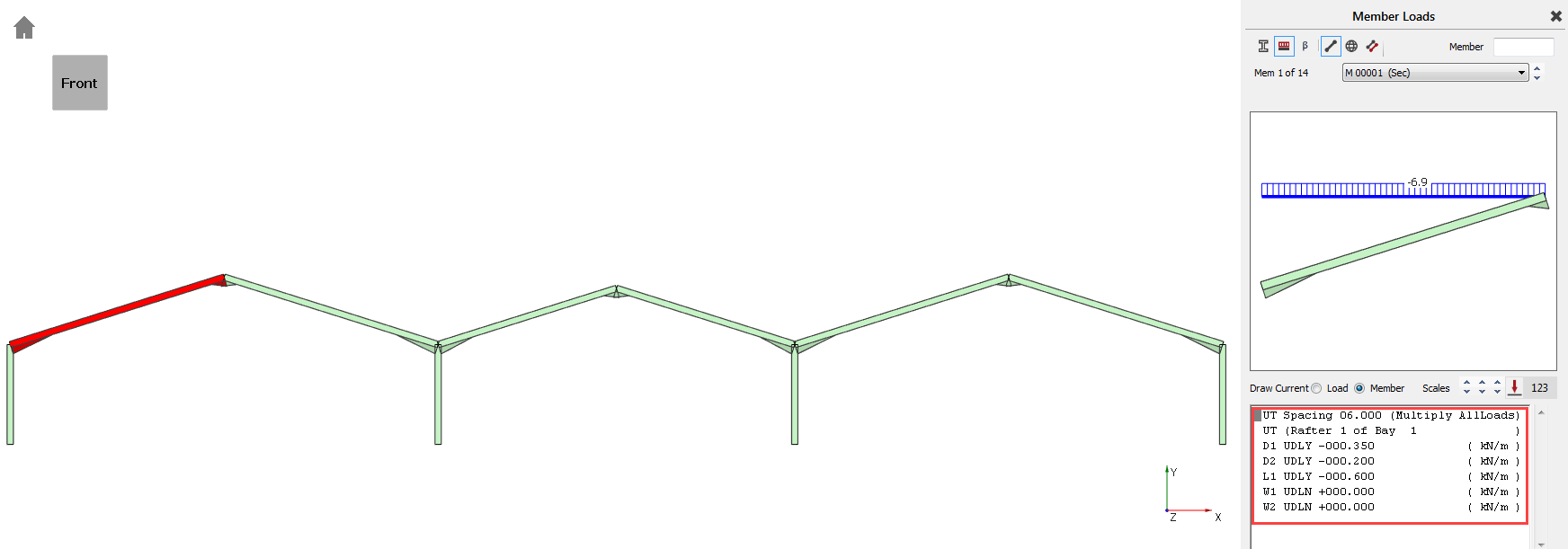
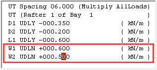
The first rafter is automatically selected, and its current loads displayed in the list of loadings window. Two wind loads have already been applied without values.
W1 will represent wind blowing from left to right. W2 will represent wind blowing on the gable end of the building (90-degrees to W1). The type of load is a UDLN, a UDL normal to the major axis of the rafter, with +ve being upwards
There is also spacing of 6 meters. Thus all loads displayed below this spacing will be multiplied by it, so ULS’s should be input as area loads (kN/m2).
Turn on the member numbers by
clicking on the Number (
 ) button in the top toolbar’s Members group to see the number of the
members.
) button in the top toolbar’s Members group to see the number of the
members.
- Apply the following loadings to M1: for W1 UDLN type 0.6, for W2 UDLN enter 0.5
- Select the second rafter, M2, by clicking on it, and apply the same values as above
- For M3 set the values of W1, and W2 to 0.5, and 0.4 respectively
- Set M4’s values to be the same as M3’s
- For M5 and M6, set the W1 value to 0.4, and the W2 value to 0.5
- Now select the left-hand column and apply a W1 load of 0.5. For the W2 value, change the “+” sign to a “-“ and give it a value of 0.7
- Select the right-hand column and apply a W1 load of +0.2, and a W2 load of +0.7
Load Cases and Combinations
From the Loads and than Loading Cases menu, select Loading Case Titles (Number of) option.
By default, there are already five (in case of using EC0 Eq. 6.10) combinations of actions and case titles generated:
- Load Case 001: 1.35 (Dead plus Services)+ 1.50 Live
- Load Case 002: Dead + Services + Live (Service)
- Load Case 003: Live Only (Service)
- Load Case 004: (Sway Stability)
- Load Case 005: 1.35 (Dead+Services) + 1.50 Live + Notional -->
We need to create four additional load cases for wind actions:
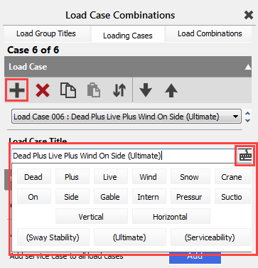
- Click on the Add load case (
 ) button and type in the load case title:
 - Load Case 006: Dead plus Live plus Wind on Side (Ultimate)
TIP! You can use the Quick
Typing Keyboard (
 ) button to create the title.
- Repeating the above process, create three additional load cases:
- Load Case 007: Dead plus Wind on Side (Ultimate)
- Load Case 008: Dead plus Live plus Wind on Gable (Ultimate)
- Load Case 009: Dead plus Wind on Gable (Ultimate)
- You should now have a total of 9 load cases.
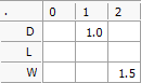
Select the Load Combinations tab at the top of the Load Case Combinations dialogue and select Load Case 006 from the dropdown list of load cases.
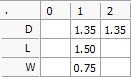
- Click into the cell corresponding to the D1 load group and then either type 1.35 or click on the 1.35 button from the Common Load Factors quick keyboard. Apply the same value of 1.35 for D2
- Click into the L1 cell and type 1.5 and then move to W1 and type 0.75
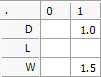
Select Load Case 007 from the dropdown list of load cases and apply a value of 1.0 for D1, and 1.5 for W1.
Select Load Case 008 from the dropdown list of load cases and apply a value of 1.35 for D1 and D2, 1.5 for L1 and 0.75 for W2.

Select Load Case 009 from the dropdown list of load cases and apply a value of 1.0 for D1 and 1.50 for W2.
Go back to the Loading Cases tab. Using the Add service case to all load cases function in the Auto-Generate Cases field by clicking on the Add button, generate all of the serviceability load cases. This will add four further load combinations for the frame.
Close the Load Case Combinations dialogue using the X button.
Viewing Frame Loading
Turn off the member numbering
by clicking on the Number (
) button.
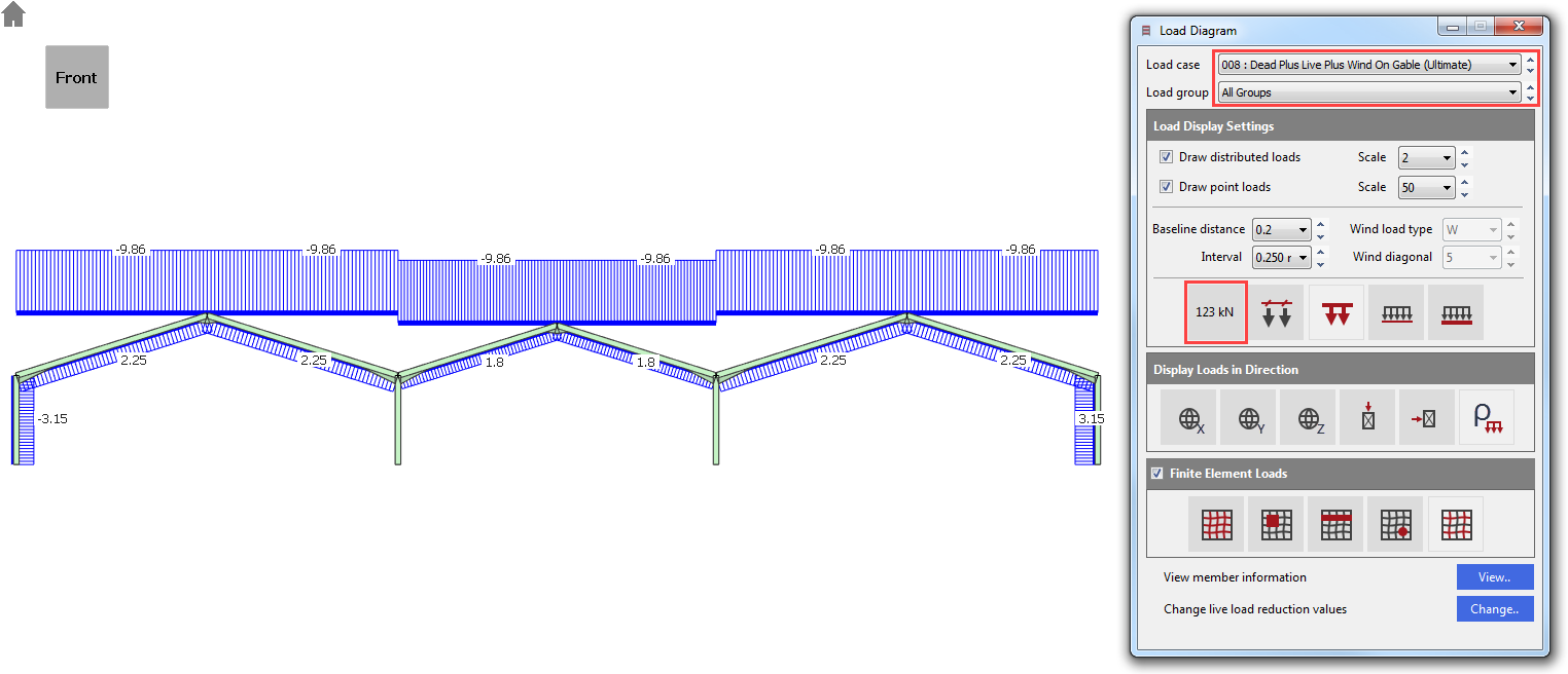
To view the frame loading
according to their load cases and load groups, click on the Frame Loads ( ) on the top toolbar.
The Load Diagram dialogue appeared.
Click on the Display Values ( ) button to show the loading values.
Click on the Load cases drop list to view the different load cases. The factored loads in the selected load case will be displayed on the frame.
Click on the Load groups to select and view a particular loading group. The unfactored loads in the selected loading group will be displayed on the frame.
Close the dialogue using the X button.
Analysis and Results
For the sake of time, the number of load cases in this tutorial will be reduced.
Go to the General tab and remove the ticks from the boxes for Add wind, Add snow and Add serviceability.
This will leave the dead and live load cases combined with notional and crane loadings but will omit those involving wind and snow loads. If you wish, you may analyse all 168 load cases and carry on through to steel design.

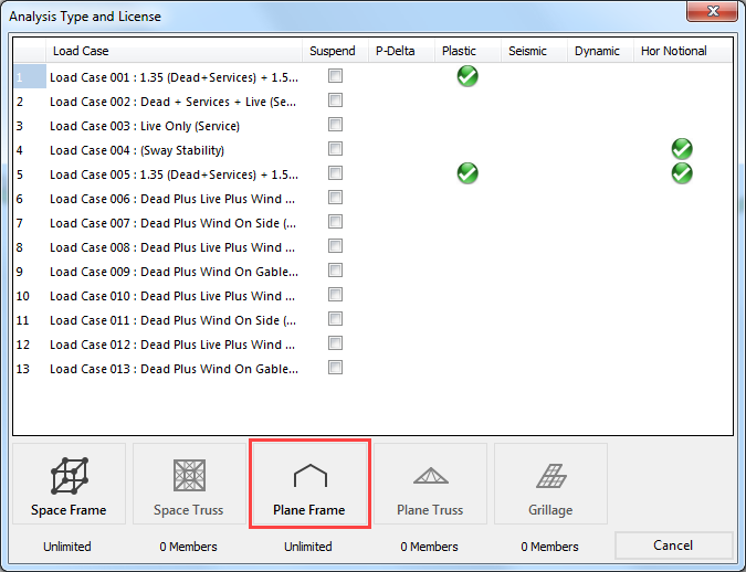
From the top menu click on the Analyse option and select the Plastic Analysis. Click OK to proceed.
Select Plane Frame from the different analysis types.
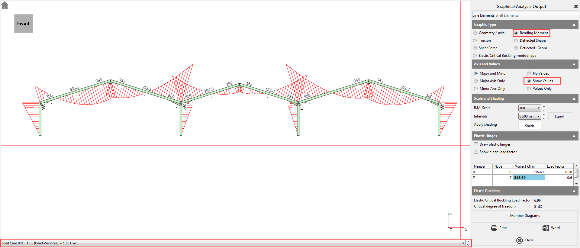
The Analysis Results
To see the analysis result, got to Output and View Tabular Output and then select for example Nodal Deflections.
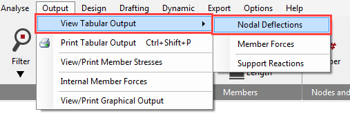
The options in the lower part of the screen enable you to control the results being displayed and are very easy to use. When there is a large amount of data the vertical scroll bar controls the view.
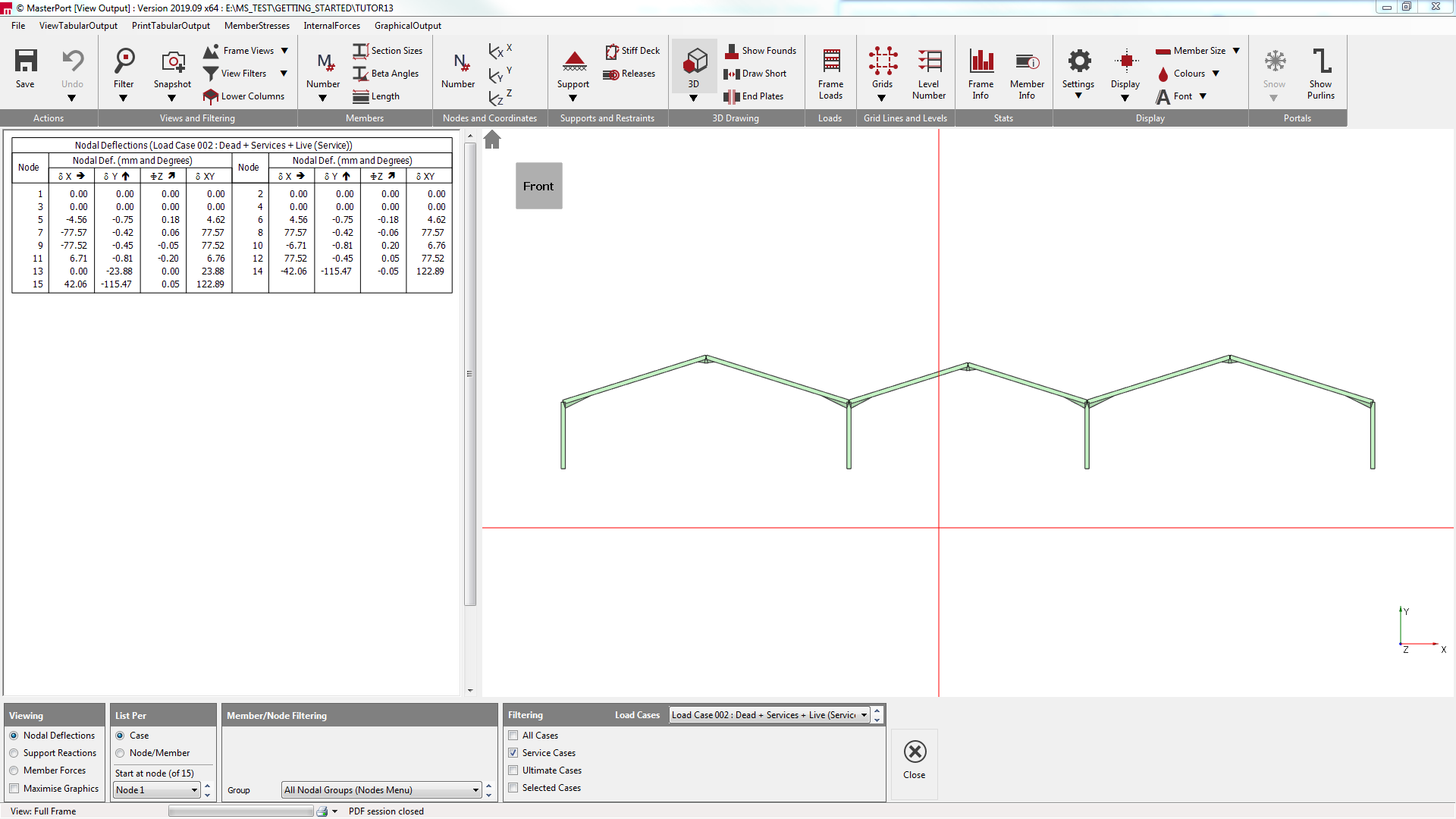
The standard method of viewing results is List per Case. This only display results in one loading case at a time. The other method is to List per Node/Member. This is useful to compare results for different loading cases for the same node or member as shown here.
Navigate between the three options on the bottom of the Tabular Output screen to view the results.
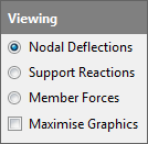
To view the results in graphical format, click on the Graphical Output from the main menu.
Select the Bending Moment diagram option. We have no members bending about the minor axis so select Major Axis Only on the right-hand panel. Select Show Values.
Using the dropdown list at the bottom of the graphical display, you will be able to scroll between the different load cases including the envelopes.
Click on the Close button to return to the main menu.
Steel Design
From the Design menu, select Steel Design.
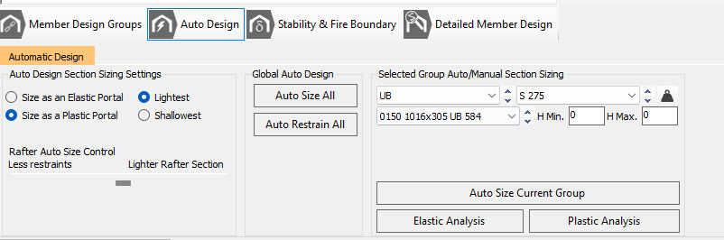
The Automatic Design tab allows you to control the type of design you prefer.
The Automatic Design defaults are set to Size as a Plastic Portal using the Lightest section that passes the design check and to opt for partial fixity 0/10/20 at the column bases.
You also have control over whether you want the automatic design to give the lightest rafter possible at the expense of more restraints or to reduce the number of restraints needed by using a slightly heavier section. Leaving the slider in the middle will give a reasonable balance between the weight and the number of restraints required.
Click on the Auto Size All ( ) to begin the automatic design process for the members in the
frame.
) to begin the automatic design process for the members in the
frame.
The necessary design briefs have been automatically set up for each of the groups of members in the frame.
The automatic design assumes that there will be cladding rails, purlins, and torsional restraints to the members on the external envelope of the frame providing adequate restraint to the columns and rafters.
Click on the Auto Restrain All ( ) button to automatically optimise the restraints.
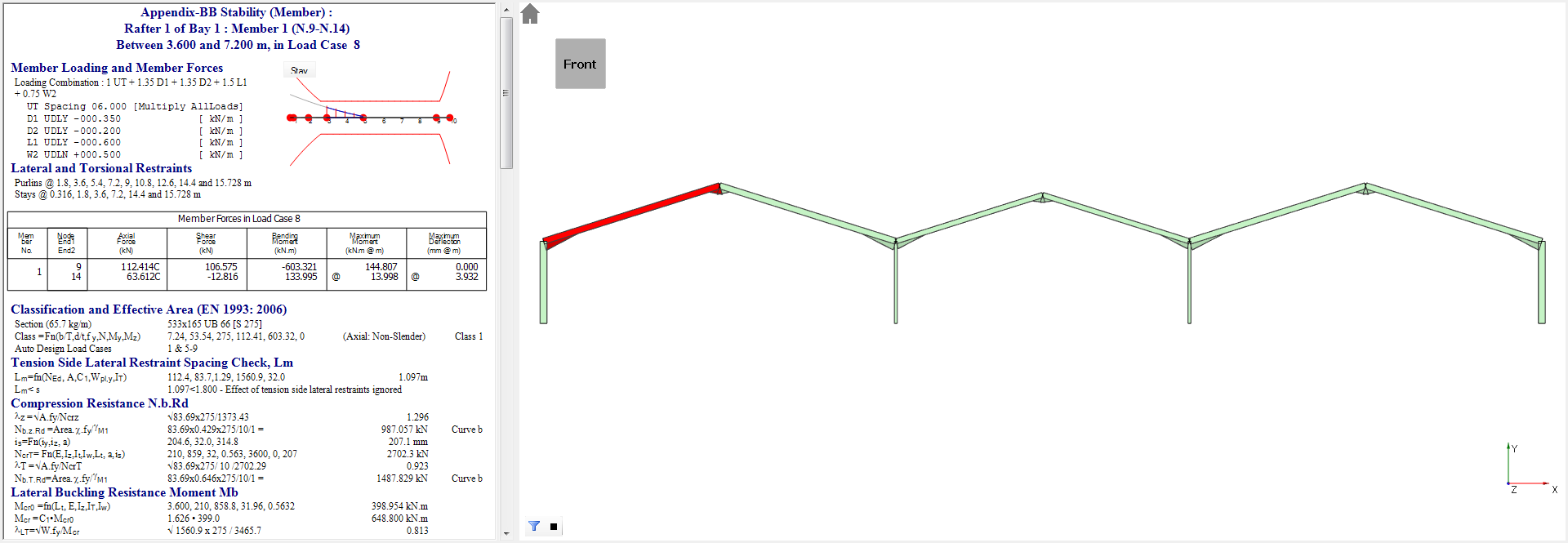
Detailed Design Outputs
Should you wish to modify or
view the designs then the Portal Frame
Final Design Stage, Purlins, Side Rails and Torsional Restraints button
(
 ) button gives you access to the individual member checks.
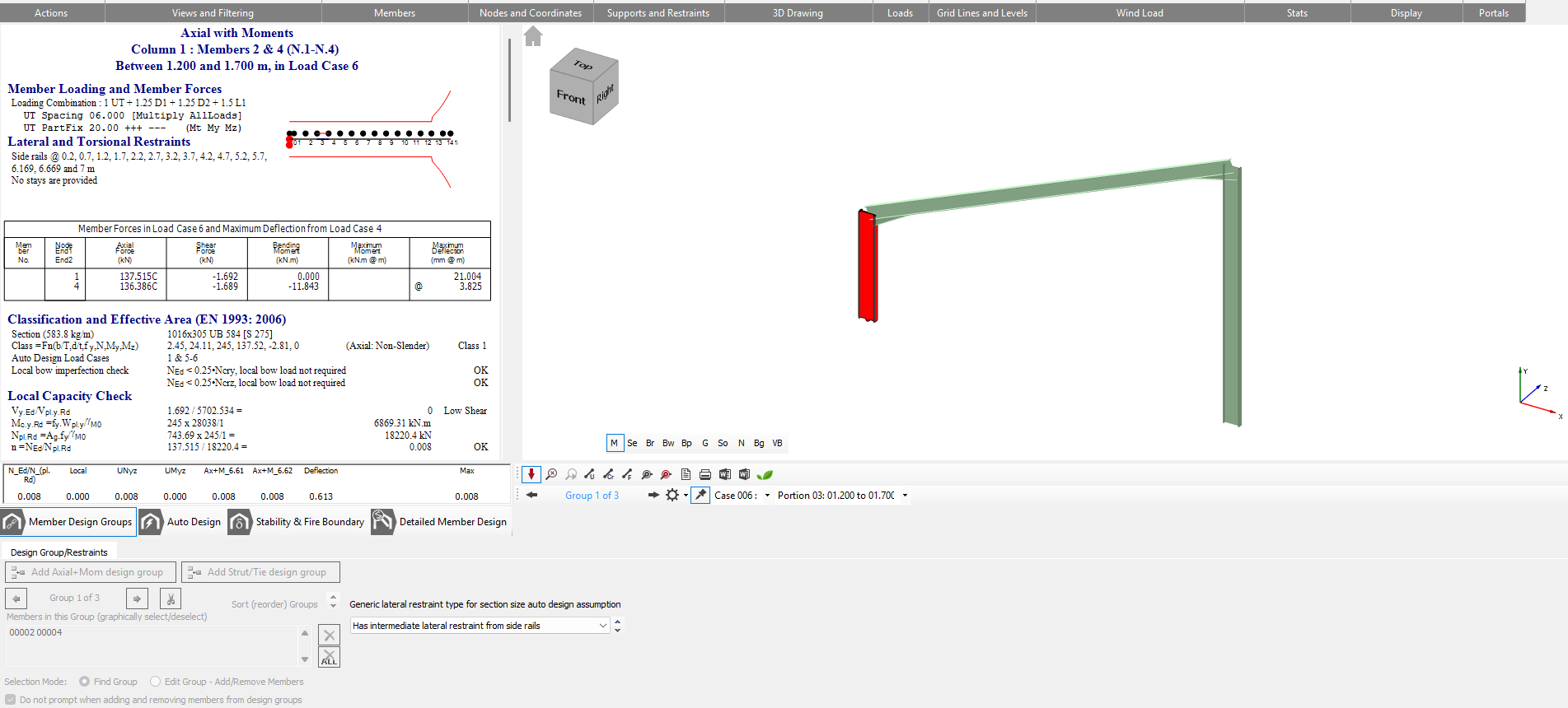
The Lateral Restraints-MinorAxis tab shows the portion of the selected member being considered along with the critical load case relevant to that section. The positions of lateral restraints can be altered if different from those automatically selected.
Clicking on any of the other members will display their corresponding calculations.
Update image - use tht he titual file and you'll see it is different at this stage-MOG
Navigate to the Briefs and Section Sizes tab and click on the Scan for failures ( ) button to see the failing members. When asked if you would
like to scan the current view, click Yes.
) button to see the failing members. When asked if you would
like to scan the current view, click Yes.
If any of the briefs fail you will be notified in a popup window. Simply click OK and you will be directed to the first failure.
Resolving Failures
In this case, the two inner columns and the M4 rafter contain failed briefs. We will now look to resolve these cases.
Select the M4 rafter member go back to the Briefs and Section Sizes tab.
Ensure that the Sort by Weight option is turned on to get the lightest section.
Select Auto Size Current Member and then Auto Restrain Current Group on the Lateral Restraints tab.
Update image- Stepehn wrong image has been used, this is Auto Design phase, where as we should be in 'Detailed meber Design' phase - MOG
After this the design results window should change from blue to white, indicating that it has passed the checks.
Click on the Move to Next Failure (
 ) button.
Select Auto Size Current Member.
Once all the items have been addressed you will need to re-analyse the frame.
Click the Plastic-Analysis on the Briefs and Section Sizes tab and then click the
Scan for failures (
) button to ensure the frame has passed all checks.
End of Tutorial