T02-1 Mono-Pitch Portal Frame
Introduction
This tutorial will require you to have access to MasterPort Plus, MasterPort Lite or PowerPad.
If you do not have access to any of this software, please contact us for a 14-day free trial to learn how MasterSeries can benefit you and your business.
Overview & Outcome
In this tutorial, we will aim to create a portal frame using MasterPort with the aim of providing you with a solid understanding of:
- Generating a portal frame
- Applying loads to the frame
- Viewing frame loadings
- Analysis and the results
- Design of steel members
Version Information
This tutorial has been written for version 2024 of the MasterSeries software suite. Subsequent versions of the software may have additional features or changes in layout, however the general procedure will remain the same.
Contact
We strive to make our tutorials as simple as possible without compromising on the technical aspects of the analysis procedure. Should you discover any errors, omissions, or are in need of additional clarification, please contact us by emailing your comments, or corrections to help@masterseries.com.
We’re social – follow us on Facebook, LinkedIn and Vimeo to keep up to date!
Loading MasterPort
To start this tutorial, launch the main program of MasterSeries.
While standing on the Programs tab, select the MasterPort from the Integrated Analysis & Design filed

Hovering over the MasterPort icon, the available integrated design options appear with small icons.
The File Selector dialogue
The File Selector dialogue will now be displayed.
You can use the File Selector to navigate in your folder tree and to select, modify or delete your existing model files or create a new one.

 ) button on the top of the file selector tree, we can see the saved
favourite folders. By selecting one of them, the file tree will immediately jump to there. By clicking the
Star icon at the end of the line, we can remove or add each of them.
The table, on the right of the File Selector (#3), lists all of the MasterFrame models contained in
the selected folder.
) button on the top of the file selector tree, we can see the saved
favourite folders. By selecting one of them, the file tree will immediately jump to there. By clicking the
Star icon at the end of the line, we can remove or add each of them.
The table, on the right of the File Selector (#3), lists all of the MasterFrame models contained in
the selected folder.The Simplified MasterPort Interface
Using the simplified MasterPort interface we can set up quickly the initial details of the portal frame.
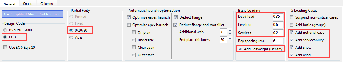
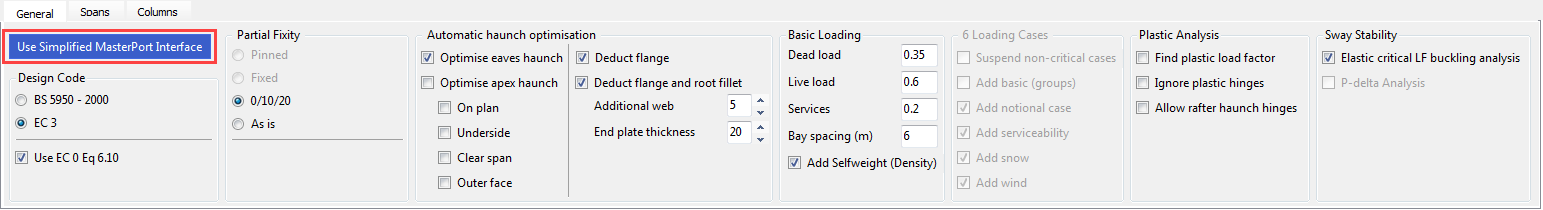
On the General tab, we can find all of the analysis and design related functionalities.
Set the following options:
- Ensure that the Design Code is set to EC 3 and check-in Use EC 0 Eq 6.10 option
- Select 0/10/20 as the partial base fixity for the portal columns
- In the Basic Loading field, type 0.35, 0.6 and 0.2 for Dead, Live and Services loads respectively and ensure that Add Selfweight (Density) is checked
- Select Add notional case, Add serviceability, Add snow and Add wind to automatically create the relevant ultimate and service load cases
- Accept the default for the haunch optimisation
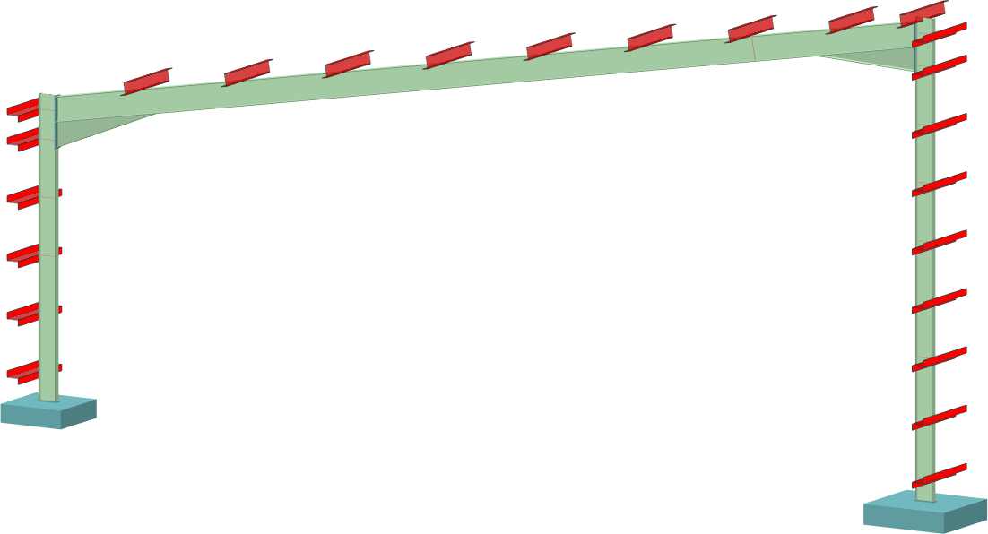
The Spans Tab – Rafter Information
On the Spans tab, we can set the details and properties of the rafters and additional features like lean-tos and cranes.
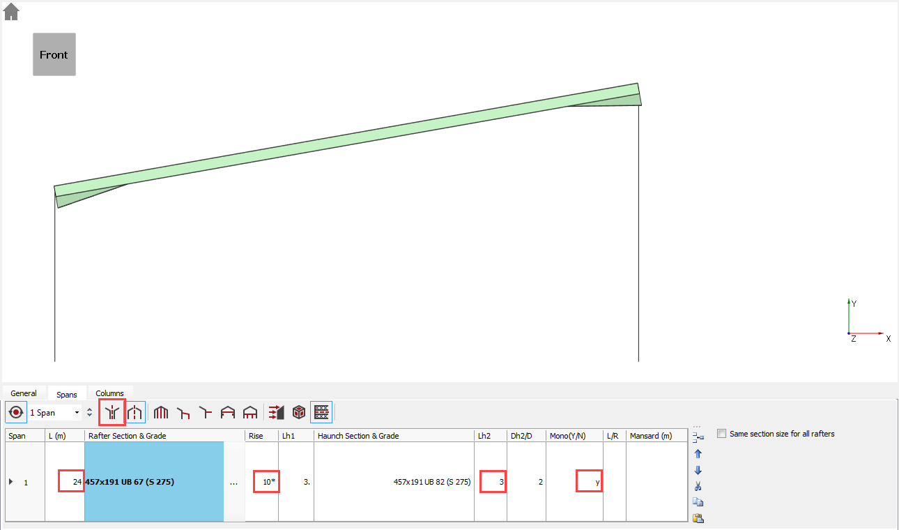
Select the Spans tab and set the following settings:
- Change the Length (L) of the span to 24 m by highlighting the cell and inserting the value
- Set Lh2 to 3 m.
- Turn off the Global Symmetry (
 ) option
 - In the Mono (Y/N) column, type Y for Span 1
- Select the Rise column and change the angle from 17.5* to 10*
We will leave the left column as the default 7m for this example. The height of the right column will automatically be set to 11.23 m.
Defining the Wind and Snow Loads
Activate the Wind/Snow tabs by
clicking on the Apply Wind/Snow Load on
Portal Frame ( ) button.
Wind loading
Click on the Wind tab.
We can manually set the wind pressures in the different directions or, by clicking on the Use MasterKey Wind q values option, we can use the inbuilt MasterKey: Wind Analysis module to automatically define the proper wind pressure values based on the location.
Check in the Use MasterKey Wind q values option.
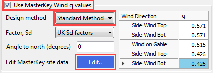
From the Design method drop list select the Standard Method and click on the Edit… button to set the site location.
MasterKey Wind Analysis module will be opened in a new window.
Site location can be selected by using the maps to pick the rough location or using the Fast Site Selection drop-down list on the Site Data tab to pick one of the cities from it.
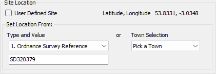
Or if you know the 8 digit Grid reference number we can input it to find the proper location.
Use SD320379 as the grid reference (Blackpool).
Lock your location click on the Lock Site button.
From the file menu, select File and Exit MasterKey Wind.
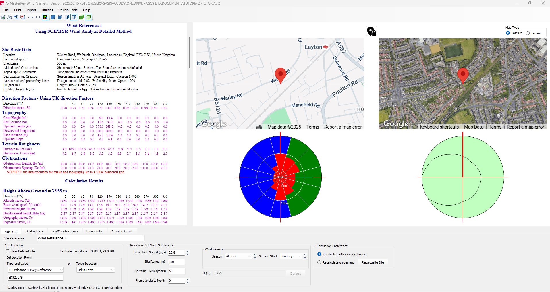
The wind pressure values are automatically updated in the table.
- Click on the 3D-Bays tab
- Set the No Equal Spacings 8
- Set the Equal Spacing (m) 6
- This allows the wind to be calculated
- Set the Current Portal 2 this will be the frame we analyse & design
Additional wind load cases are generated to include internal pressure (Cpi) giving the P group of wind cases and internal suction (Csi) giving the S group of wind cases. Therefore there are three sets of wind load cases developed. Note that there is no need to place a “-“ sign in front of the suction coefficient.
Turn on the Wind ( ) button from the top toolbar’s Wind Load group to display the wind
loading.
) button from the top toolbar’s Wind Load group to display the wind
loading.
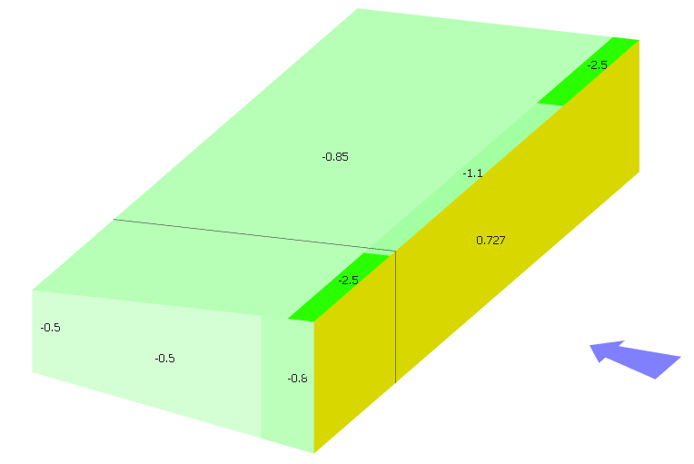
Using the Direction (
 ) function you can examine the wind in each direction. Using
the wind loading visualisation options (
) function you can examine the wind in each direction. Using
the wind loading visualisation options ( ) you can see the generated wind coefficients, pressures and
zones on each surface.
) you can see the generated wind coefficients, pressures and
zones on each surface.
Snow loading
Click on the Snow tab and set the followings:
· Type 0.5 in the Zone number NA.1 value box (see Figure NA.1 of UK NA to EN 1991-1-3)
· Type 120 for the Site Altitude (m)
The program will use these values to evaluate the symmetrical and asymmetrical snow loadings in accordance with the selected standard.
Select the Snow Load ( ) button in the Portal
group, of the top toolbar, to see a graphical representation of the snow load.
) button in the Portal
group, of the top toolbar, to see a graphical representation of the snow load.
You can scroll through the different load cases (L0 – L5) and see the different snow distributions using the dropdown list to the right of the Snow Load button. In this instance, only L0 is used.
Viewing Frame Loading
Turn off the snow loading and wind loading and you will return to your 2D model.
To view the frame loading according to their load cases and load
groups, click on the Frame Loads
(
 ) on the top toolbar.
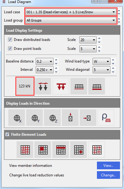
The Load Diagram dialogue appeared.
Click on the Display Values ( ) button to show the loading values.
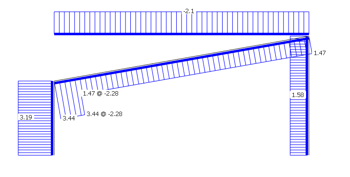
Click on the Load cases drop list to view the different load cases. The factored loads in the selected load case will be displayed on the frame.
Click on the Load groups to select and view a particular loading group. The unfactored loads in the selected loading group will be displayed on the frame.
Close the dialogue using the X button.
Viewing Options
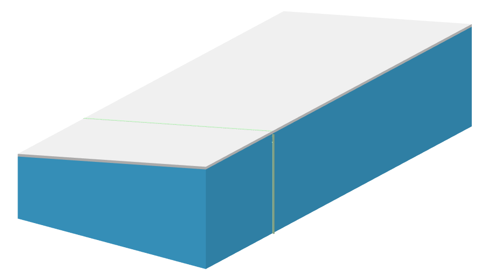
To see the 3D view of the
structure click on the 3D
( ) button in the 3D Drawing
group of the top toolbar.
) button in the 3D Drawing
group of the top toolbar.
Click on the Draw Purlins ( ) button in the Portals
group to display the layout of the purlins and side rails.
) button in the Portals
group to display the layout of the purlins and side rails.

Analysis and Results
From the top menu click on the Analyse option and select the Plastic Analysis. Click OK to proceed.
The Analysis Results
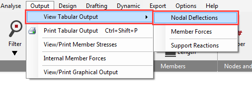
To see the analysis result, got to Output and View Tabular Output and then select for example Nodal Deflections.
The options in the lower part of the screen enable you to control the results being displayed and are very easy to use. When there is a large amount of data the vertical scroll bar controls the view.
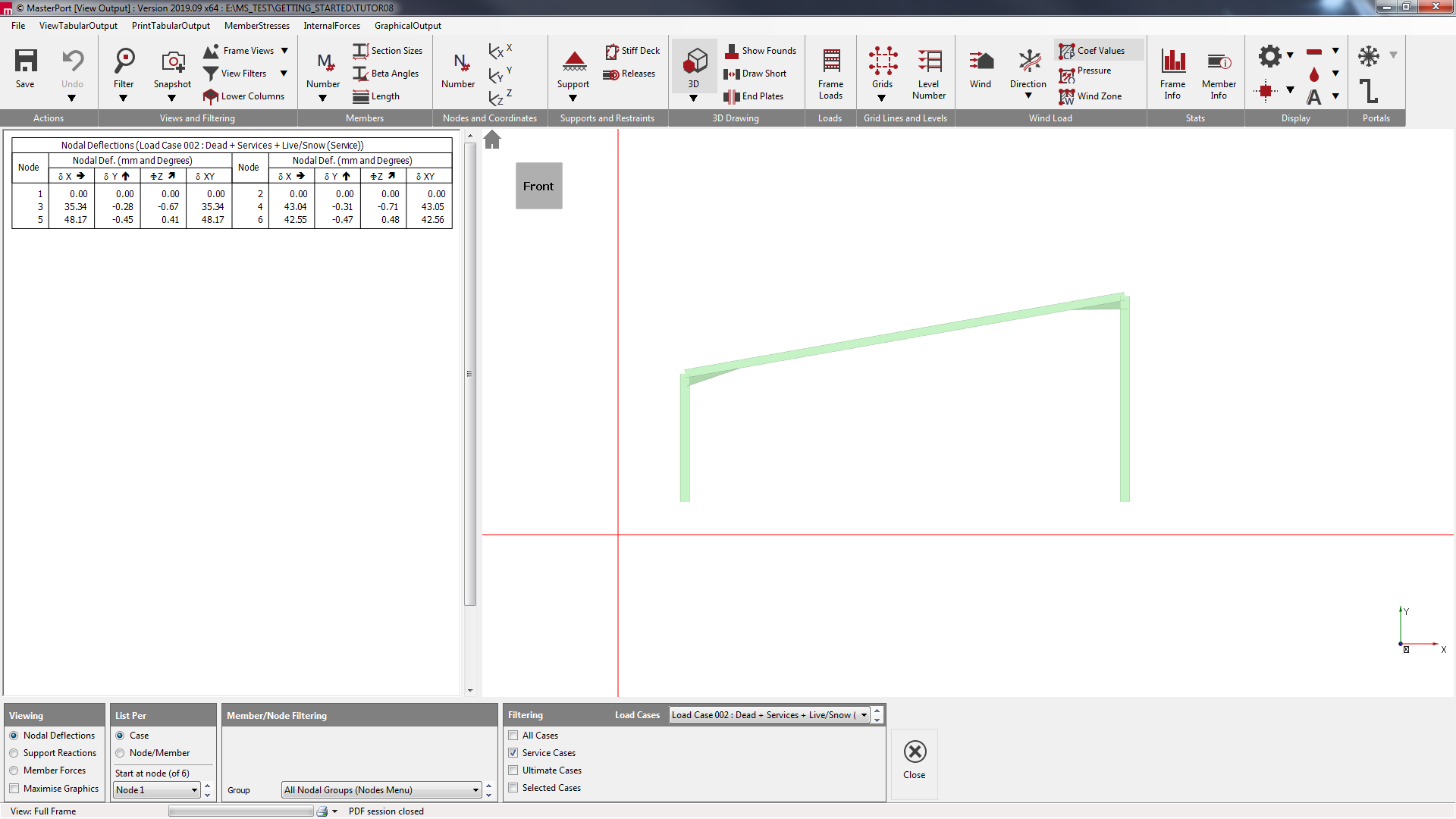
The standard method of viewing results is List per Case. This only display results in one loading case at a time. The other method is to List per Node/Member. This is useful to compare results for different loading cases for the same node or member as shown here.
Navigate between the three options on the bottom of the Tabular Output screen to view the results.
To view the results in graphical format, click on the Graphical Output from the main menu.
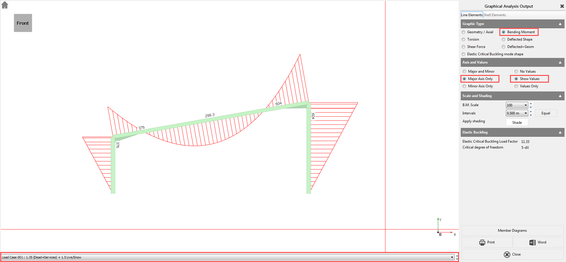
Select the Bending Moment diagram option. We have no members bending about the minor axis so select Major Axis Only on the right-hand panel. Select Show Values.
Using the dropdown list at the bottom of the graphical display, you will be able to scroll between the different load cases including the envelopes.
Click on the Close button to return to the main menu.
Analysis and Results
From the Design menu, select Steel Design.
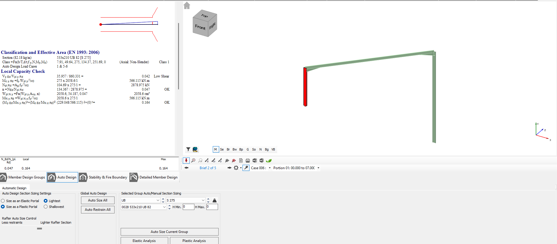
The Automatic Design defaults are set to Size as a Plastic Portal using the Lightest section that passes the design check and to opt for partial fixity 0/10/20 at the column bases.

You also have control over whether you want the automatic design to give the lightest rafter possible at the expense of more restraints or to reduce the number of restraints needed by using a slightly heavier section. Leaving the slider in the middle will give a reasonable balance between the weight and the number of restraints required.
Click on the Auto Size All (
 ) to begin the automatic design process for the members in the
frame.
) to begin the automatic design process for the members in the
frame.
The program designs the frames and at the end of the process states that the frame is fully elastic in this particular case.
The automatic design assumes that there will be cladding rails, purlins, and torsional restraints to the members on the external envelope of the frame providing adequate restraint to the columns and rafters.
Click on the Auto Restrain All ( ) button to automatically optimise the restraints.
Manual Restraining
Should you wish to modify or
view the restraint locations then the Detailed Member Design
( ) button gives you access to the individual member checks. For practice, we shall modify
the rafter to have a purlin spacing of 2.8
meters.
) button gives you access to the individual member checks. For practice, we shall modify
the rafter to have a purlin spacing of 2.8
meters.
Click on the Portal Frame Final Design Stage, Purlins, Side Rails
and Torsional Restraints button (
) and select the rafter in the graphics window.
Click on the Lateral Restraints tab.
In the Equal Spc box, input a value of 2.8 and click on Auto Restrain Current Group.
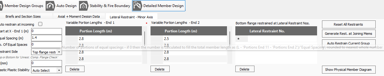
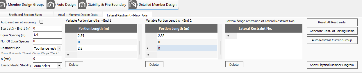
MasterPort will calculate the optimum restraint locations for this group of members. If there were more than one member in the group, then the optimum restraint positions that suits all members in the group would be chosen.
The deflection limit is currently set to L / 360. We could change the limit to L / 250 but that is restrictive. Instead, we’ll modify the deflection limit for different loading cases.
Move to the Axial with Moment tab. Click on the Def Limit cell and click on the appeared thee dots button to open the Steel Design Deflection Limits dialogue.
In the table type Portal Rafters into the Title cell for group number 4 and input the values 360 and 250 into the Live and Dead + Live cells respectively.
Close the dialogue by clicking the X button.
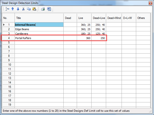
Input 4 in the Def Limit input box to indicate that we wish to use deflection group 4.
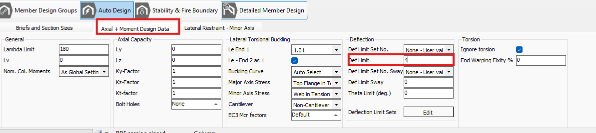
The value of deflection has been decreased however it is still a problem, so we need to stiffen the structure.
Go back to the Briefs and Sections tab.
Ensure that the Sort by Weight option is turned on to get the lightest section.
Select Auto Size Current Member and then Auto Restrain Current Group on the Lateral Restraint - Minor Axis tab.
Select Plastic-Analysis on the Briefs and Sections Sizes tab to re-analyse the frame.
Checking For Failures
Using the Scan for failures function, the program will highlight the first member (if any) to have failed.
Navigate to the Briefs and Section Sizes tab and click on the Scan for failures ( ) button to see the failing members.
All design briefs will be scanned and checked for failures. If a failure is found, repeat the basic sizing and design process:
i. Auto Size Current Member
ii. Auto Restrain Current Group
iii. Plastic Analysis
iv. Scan for Failures
v. And repeat if necessary

Printing The Design Output
You can print the calculations for each group of members, by selecting which individual checks you wish to print for each group.
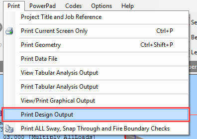
Select the Print Design Output option from the Print menu and select Include All.
The program will run through all the checks for all portions for this group of members and check whether each portion passes or fails. Rather than print all calculations for all portions of all members, you can optimise the print out by printing only the critical portion for each member.
Check the Critical Portion Only checkbox and click on the Auto Select button.
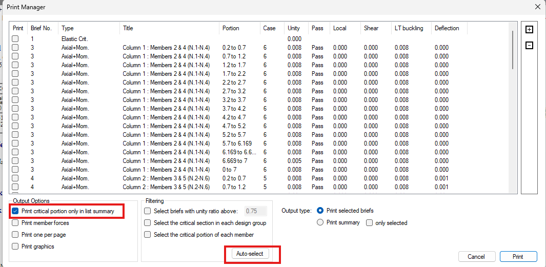
The AutoSelect automatically selects the critical portions from each check.
Selecting to Print List (Summary) will print the list as seen at the bottom of the screen with a single line for each check.
Selecting to Print Selected Checks will print out comprehensive calculations for each highlighted portion check.
Click on the Cancel button in this instance.
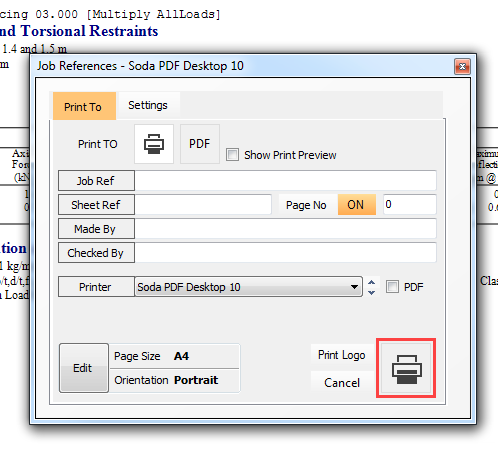
Now, select the Print Current Screen Only option from the Print menu.
Select the Print button in the Job References dialogue box and the brief for the current member will be printed.
Adding the Wind and Snow Loads in MasterPort Lite
For users who do not have MasterPort Plus, the wind and snow loading cases will not be automatically applied. This part of the Tutorial presents, how can you create the wind and snow loadings manually.
To have direct access to the loading functionalities, we have to turn on the Use Simplified MasterPort Interface function on the General tab.
Adding the Member Loadings
To manually create member loading, select Member loading – Member, Global and Copy to option from the Loads / Member Loading menu.
Even though the automatic wind and snow load generation is not available in MasterPort Lite, the frame generator has already created the necessary number of wind load definitions and assigned them to the proper wind load groups.
Turn off the 3D (
 ) view from the top toolbar and select Flame Loads (
 ) button to display the frame loading on the graphical area.
Change the top drop list of Load Case to the first item, All Loading Cases to show all of the applied
loads with default values (without safety factors) and change the second drop list to Load Group W1 : Wind Load to see only the W1 : Wind Load group.
Click on the left column to define the wind loading on it.
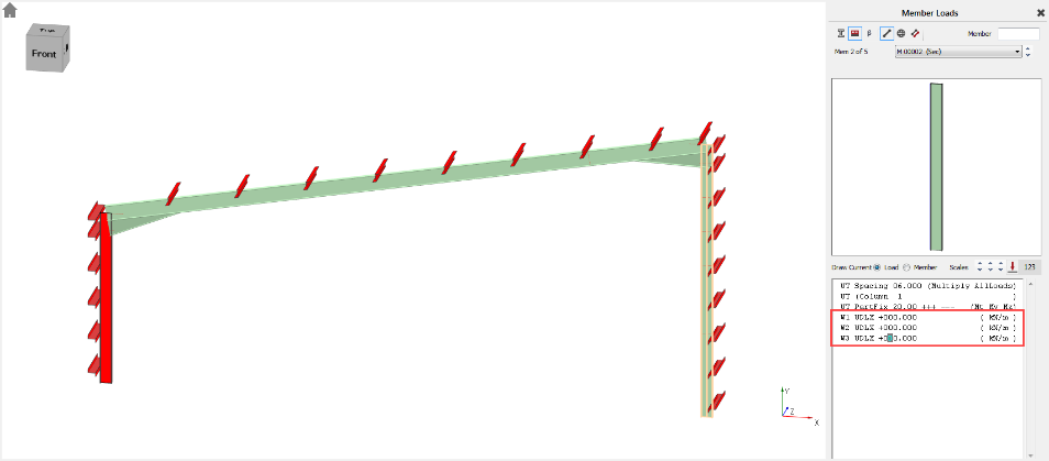
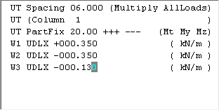
- Edit the first load W1 UDLX +000.000 (kN/m) to W1 UDLX +000.350 (kN/m).
- Edit the second load W2 UDLX +000.000 (kN/m) to W2 UDLX -000.350 (kN/m).
- Edit the third load W1 UDLX +000.000 (kN/m) to W3 UDLX -000.130 (kN/m).
If you change the Load group drop list of the Load Diagram dialogue to W2: Wind load or W3: Wind load you can check the placed loading on the frame model as well. If it is needed you can increase or decrease the scale of the distributed loads.
Click on the right column and define the following wind loading on it:
Edit the first load to W1 UDLX +000.180 (kN/m).
Edit the second load to W2 UDLX +000.350 (kN/m).
Edit the third load to W3 UDLX -000.270 (kN/m).

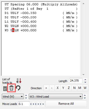
Click on the rafter to define the wind and snow loadings on it.
As the wind loading is not a uniform distributed load in the + and – X directions, at first we have to delete the created W1 and W3 UDLN loading definitions.
Set the cursor on the W1 UDLN
first and click on the Delete
current loading ( ) button.
Repeat the same for W3 UDLN.
Click on the PTRY (
 ) button four times to add four new partial distributed load
to the list (two for W1 and two for W3).
) button four times to add four new partial distributed load
to the list (two for W1 and two for W3).
Set the cursor on the first new PTRY load and change the load to W1 PTRN +000.380 0.000 2.280 +000.380 to assign to load to the W1 wind load group and set the intensity and the positions.
The units for this load are as follows:
- N – local axis of the member parallelly to the web
- Load value at the start of load (kN/m)
- Distance to start of load (m) from the End 1.
- Distance to end of load (m) from the End 2.
- Load value at end of load (kN/m)
Set the cursor on the second PTRY and change the load to W2 PTRN +000.160 2.280 0.000 +000.160.
Change the other two PTRY to the following:
W3 PTRN +000.360 0.000 22.09 +000.360
W3 PTRN +000.700 22.09 0.000 +000.700
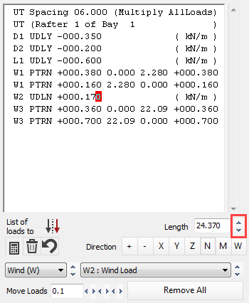
Set the cursor on the W2 UDLN and change the load to W2 UDLN +000.170 and using the Sort: Move current load arrow buttons move down to the proper position.
We will use the automatically created L1 UDLY -000.600 (kN/m) as a snow load.
Using the X button, close the Member Loads and the Load Diagram.
Generate All Load Cases
From the Loads and Loading Cases menu, select Loading Cases Titles.
We will use the Auto-Generate Cases function to create all loading cases.
To open the Automatic Load Case Generator dialogue, click on the Edit… button of the Create/edit all load cases function in the Auto-Generate Cases field.
We can use the default Load Case Template to generate the load cases.
We will use the following templates and generation settings. To modify a template select it at first in the Select Load Case Templates to Generate table and update the settings below.
- Dead + Live: leave on default
- Live Only: leave on default
- Dead + Live + Wind

o Selected Load Groups: D0, D1, L1 (Leading) and W-All (Leading)
o Load case type: Ultimate+Service
o Ultimate case type: STR/GEO Set B eq. 6.10
o Service case type: Characteristic
o Horizontal notional forces: Add as per wind
- Dead + Wind
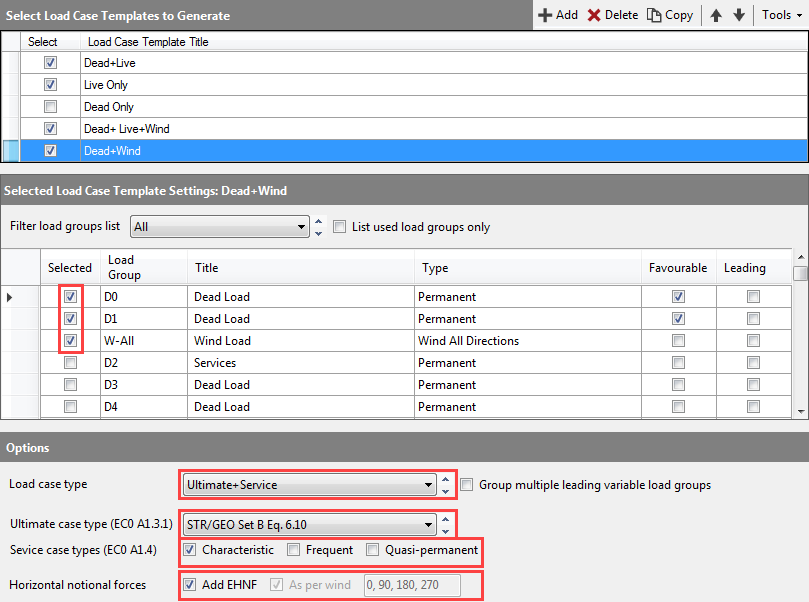
o Selected Load Groups: D0, D1, W-All
o Load case type: Ultimate+Service
o Ultimate case type: STR/GEO Set B eq. 6.10
o Service case type: Characteristic
o Horizontal notional forces: Add as per wind
To generate all load cases and replace the existing ones, click on the Replace button.
End
of Tutorial