T01-9 Seismic Design
Introduction
MasterFrame: Space Frame Analysis is a state-of-the-art structural space frame analysis software program, incorporating many advanced analysis features to help you meet the increasingly strenuous and demanding requirements of modern design codes, including Eurocode and British Standard. The MasterFrame: Dynamic Analysis is an add-on for MasterFrame to analyse and design your models for the effects of dynamic behaviour.
The MasterFrame:
Dynamic Analysis module uses the MasterFrame model to assess the natural
frequencies of the structure and then evaluates your structure in line with
either the Steel Construction Institute or Concrete Society design guidance.
The MasterSeries: Seismic Analysis module allows you to employ various methods
of seismic analysis with standard MasterFrame models. This allows you to
integrate the seismic analysis and design with the design of other elements in
your structure, within a single model.
Overview & Outcome
- Frame generation
- Carrying out modal analysis
- Carrying out spectrum response analysis
- Viewing the results
Loading MasterFrame
To start this tutorial, launch the main program of MasterSeries. While standing on the Programs tab, select the MasterFrame from the Integrated Analysis & Design filed.

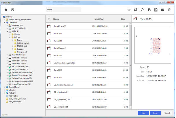
The File Selector Dialogue
The Frame Generation Menu
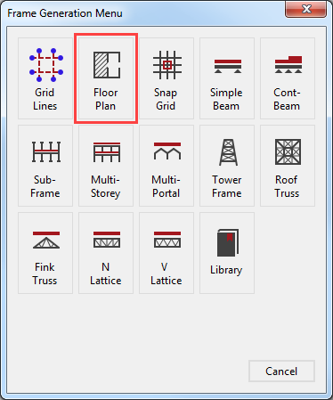
To generate our start-up frame, select the Floor Plan button.
For More information click 📑 Starting a new Frame
The Start-up Frame
The Floor Layout pre-processor is now displayed.
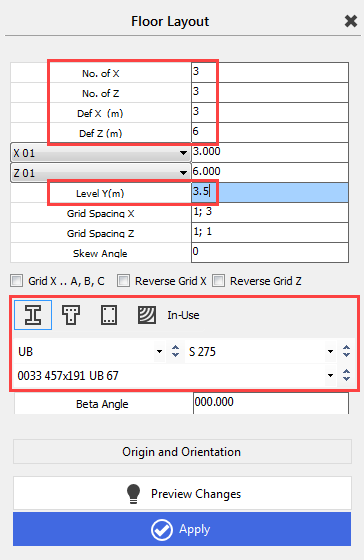
You can click in any text box to set the focus to it; you can also move from one box to another using the cursor up and cursor down keys.
Enter 3, 3, 3 and 6 m for the No. of X, No. of Z, Def X (m) and Def Z (m) edit boxes respectively.
Ensure that the Level Y (m) cell is set to 3.5.
Ensure the default
cross-section is a Steel (
 ) and 457x191 UB 67
S275.
) and 457x191 UB 67
S275.
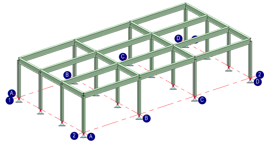
Select Apply ( ) to generate the frame. Close the Floor Layout dialogue by clicking on the X.
Editing the Frame Geometry
Adding the Columns
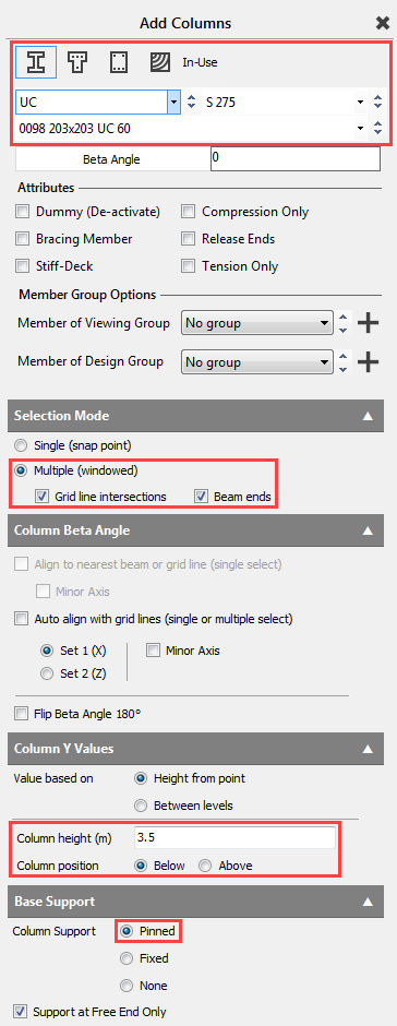
From the Create main menu select Add Columns function.
Set the Steel (
) section type to UC
and change the size to 0098 203x203 UC
60 and also, set the steel grade to S275.
In the Selection Mode, set the Multiple (windowed) mode and ensure both Grid line intersections and Beam ends are selected.
Set the Column height (m) of the column to 3.5m and the Column position to Below. Since this column will be at the bottom of the frame, add a Column Support as Pinned.
Window select the whole level.
Using the X button, close the Add Columns dialogue.
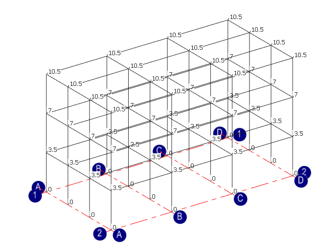
Creating Multiple Stories
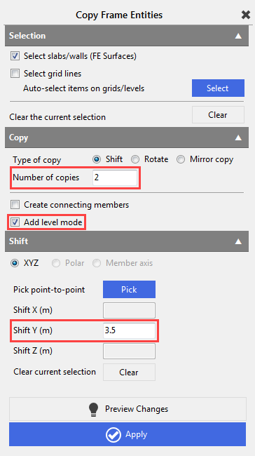
From the Create main menu select Copy Add Members… function.
Window the whole frame, to select it.
Set the Number of copies to 2 and check in the Add level mode.
Set the Shift Y (m) to 3.5 m and then select the Apply button.
Close the Copy Frame Entities dialogue with the X.
Setting Up Floor Stiffness
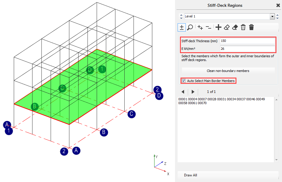
To effectively brace the levels in the horizontal plane, we will place stiff-decks on each of the levels.
From the main Create menu, select Add Stiff-deck, Semi-rigid.
Place
the frame in front view by selecting the Top side of the viewing cube (
 ).
).
Label group Level 1.
Set the Stiff-deck Thickness (mm) to 150 mm and E kN/mm2 to 26 kN/mm2.
Switch
to Add/remove items (
 ) mode, check-in Auto Select Main Border Members checkbox
and then window the whole first floor.
) mode, check-in Auto Select Main Border Members checkbox
and then window the whole first floor.
Using
the Add New Group (
 ) button add a new group and repeat the process for Level 2 and Level 3.
Close the Stiff-Deck Regions dialogue with the X.
Applying Loads
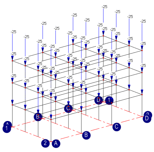
For simplicity, we will use nodal loadings to demonstrate how we can account for them in dynamic analysis.
Loads are applied to the structure by assigning them to load groups. Factors can be applied to these loads groups in the dynamic section. This will account for loading as part of the mass of the structure during the modal analysis.
From the main Loads menu, select the Nodal Loading option.
Place the frame in front view
by selecting the Front side of
the viewing cube (
).
Now select all the nodes on each of the 3 levels of the structure by windowing them in the front view.
In the FY edit box enter a load of -25 kN.

Change the load group of these nodal loads to Dead (D) and ensure the specific group is D1: Dead Load.
Close the Nodal Loading
dialogue with the Close ( ) button.
Analysis methods
In MasterFrame, we can use the following two analysis methods to apply the seismic loading:
- · Lateral Force Method
- Lateral Force Method is a simplified analysis method of seismic loading. It can be used for those structures where the first vibration mode is dominant for each horizontal directions and they meet the criteria for regularity in elevation (EN 1998-1 4.3.3.2).
Lateral Force Method doesn’t require dynamic analysis
- · Modal Response Spectrum Analysis
Modal Response Spectrum Analysis (MRSA) is applicable to all types of building. MRSA requires dynamic analysis and all of the significant vibration modes need to be taken into account (EN 1998-1 4.3.3.3)
At first, we will use the MRSA to apply the seismic forces to the structure and then quickly we will see the Lateral Force Method as an alternative calculation mode.
Modal Response Analysis Spectrum
The MRSA requires dynamic analysis to determine the significant vibration modes of the structures.
From the Analysis main menu, please select the Dynamic Analysis option.
Click Yes when prompted to save.
The dynamic analysis options are placed on the bottom tabbed dialogue.
To determine the seismic forces we will use the Natural Frequency option first and then the Response Spectrum Analysis option.
Calculation of the natural frequencies
Using the functions of the Natural Frequency tab, we will determine the necessary amount of vibration modes.
As a first step, we have to define the masses for the dynamic calculation.
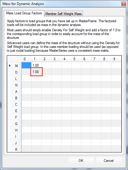
Using the Edit Mass Load Contribution button, the previously defined load groups can be included as a mass applying factors to them.
In general, the mass factors are the same as the combination factors in the seismic load combinations.
To apply the placed nodal loads as a mass, enter 1.0 in the D1 cell corresponding to the D1: Dead Load.
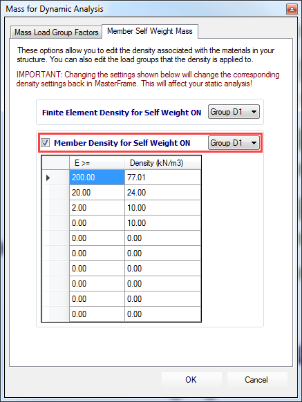
MasterFrame has the ability to automatically calculate the mass from the self-weight of the structure. Move to the Member Self Weight Mass tab and ensure that Member Density for Self Weight ON checkbox is selected and the self-weight is assigned to the inclouded D1 load group.
Save your settings and close the dialogue by clicking on the OK button.
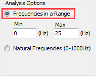
To calculate the significant vibration modes, we have to set the frequency range for the calculation in the Analysis Options field.
Using the Natural Frequencies (0-1000Hz) option, MasterFrame will determine all of the natural vibration shapes, however, in case of a large model, it might take notable calculation time.
It is recommended to use Frequencies in a Range option in order to calculate only the vibration modes in the specified range first and then extend the limits if it is needed.
Set the Min limit to 0 Hz and the Max
to 25 Hz and then click on the Analysis (
 ) button to start the calculation.
What we need to check first is the mass participation in the relevant directions. According to the Eurocode 8, in all of the relevant directions, the sum of the effective modal masses for the modes need to take into account at least 90% of the total mass of the structure.
In our example we are only considering the horizontal seismic effect,
so we only have to ensure that the total mass participation in the X and Z directions are higher than the required 90% limit.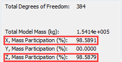
If not, the upper frequency limit needs to be increased and the analysis must be repeated until you reach the limit in all of the directions.
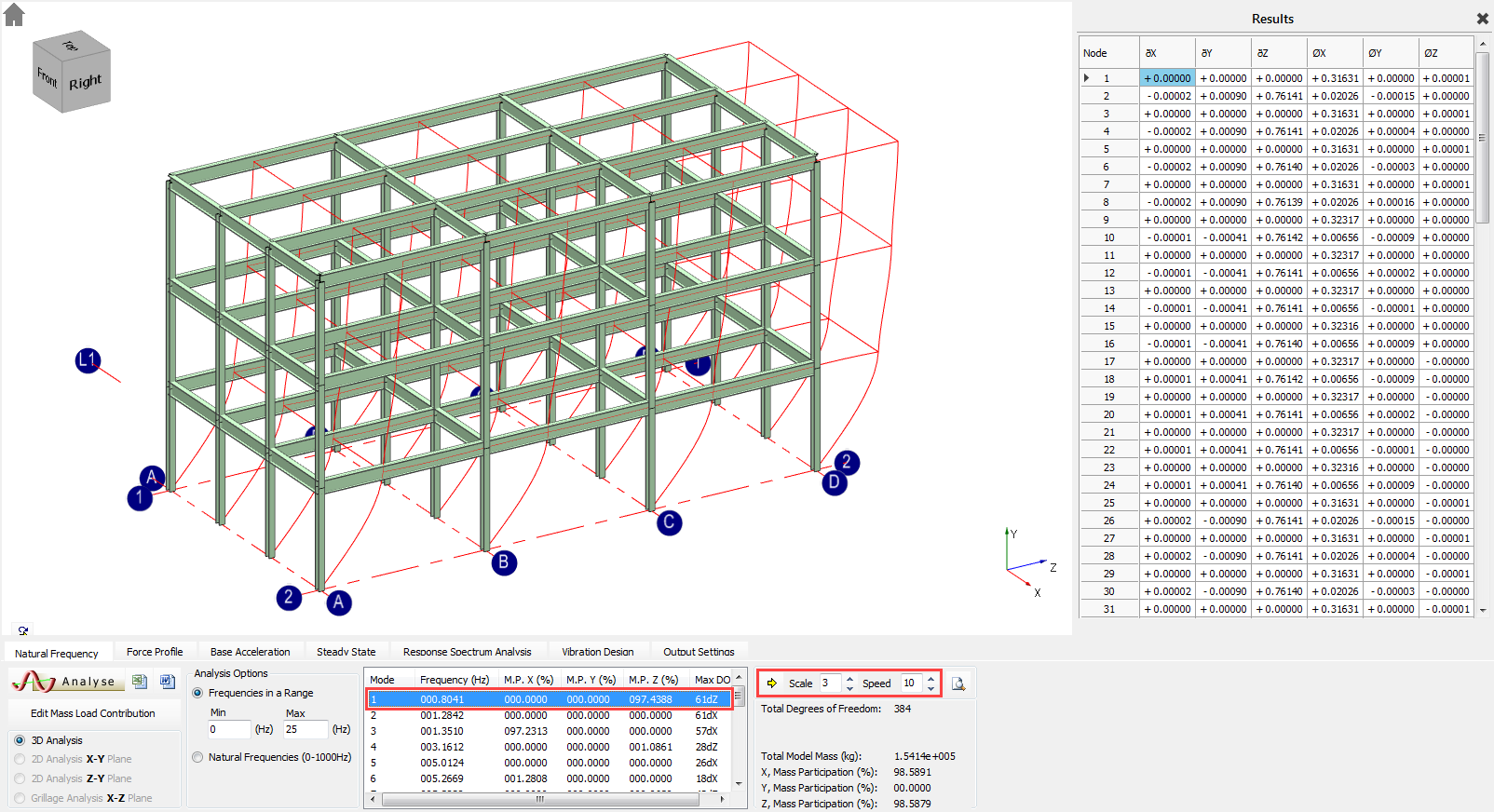
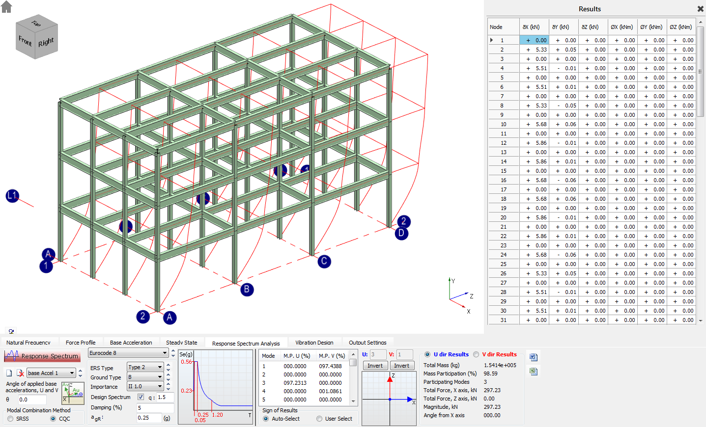
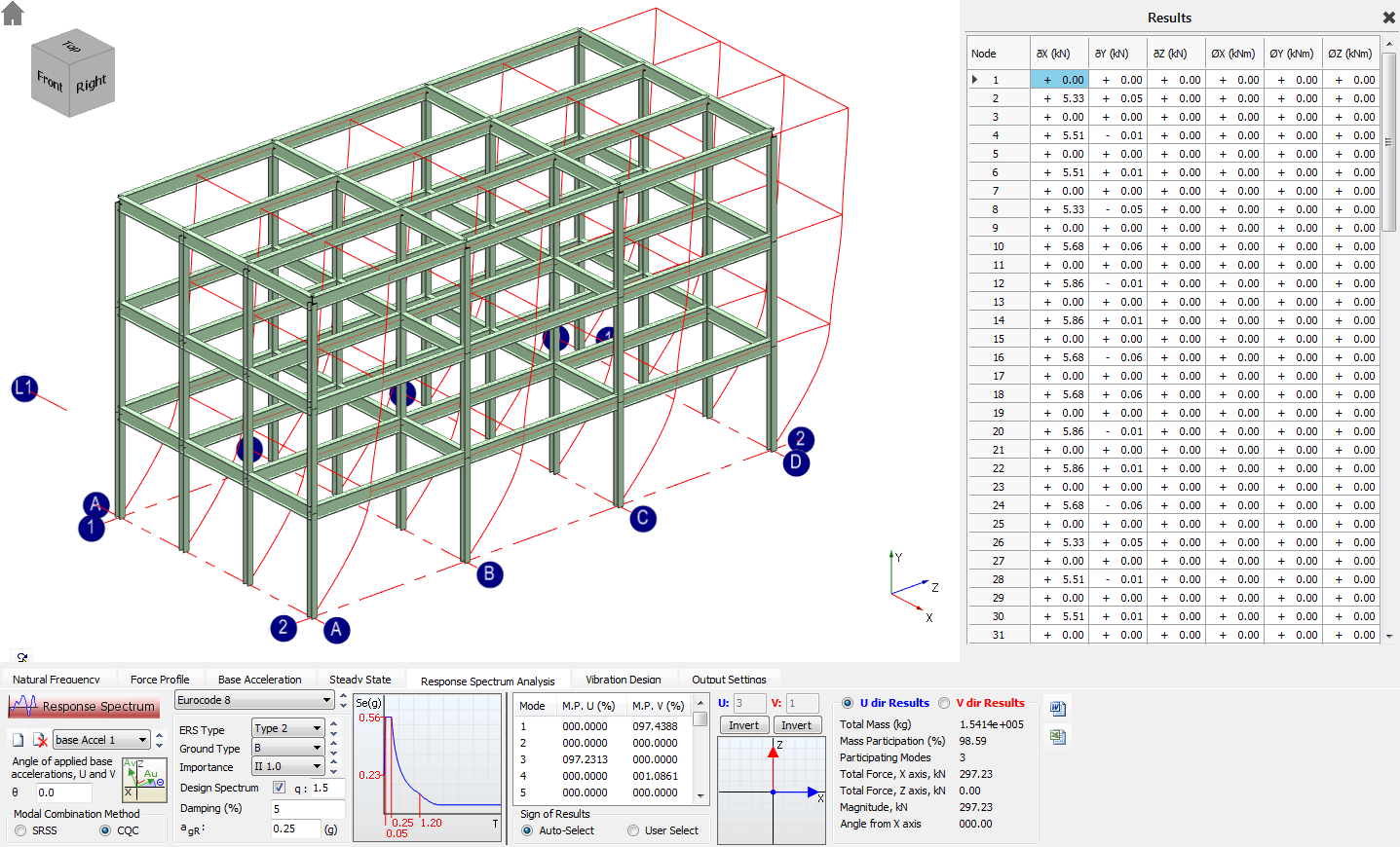
In the middle of the tab, each of the vibration modes is represented and natural frequency in the Frequency (Hz) column and the mass participation in each of the directions (M.P. X, M.P. Y and M.P. Z (%)) of them can be checked.
Selecting one of them, the graphical area will show us the shape of the vibration mode and the Result panel will list the displacements of each of the nodes.
Pressing the Play (
 ) button, we can see the selected modal shape in motion. The scale
and speed of the displayed mode shape can be changed.
) button, we can see the selected modal shape in motion. The scale
and speed of the displayed mode shape can be changed.
Response Spectrum Analysis
After we determined the significant vibration modes we can move forward to the Response Spectrum Analysis tab.
By clicking on the Create (
 ) button, we have to create a new dynamic load case first.
By default, the angle of the applied base accelerations (U, V) are parallel with the main horizontal X and Z axis. If your model’s main perpendicular axes are not parallel with the main X and Z axis than you should set the angle of the base accelerations to them by overwriting the θ value.
Change the Modal Combination Method from SRSS to CQC (a more modern and accurate approach).
Setting the Response Spectrum
To set the response spectrum, at first we have to select the design code from the droplist, which is the Eurocode 8 in our example.
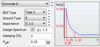
For response spectrum type, select the most used Type 2 and for Ground Type the B and for Importance factor the general II 1.0.
As we would like to check the earthquake resistance of our structure in accordance with the Low-dissipative structural behaviour concept, check-in the Design Spectrum checkbox and set the value of q behaviour factor to 1.5, which is the upper limit of the low-dissipative structures by the Eurocode 8.
Note: In the concept of Low dissipative structural behaviour, the resistance of the steel members and of the connections should be evaluated in accordance with EN 1993 without any additional requirements.
We will leave the value of the Damping (%) factor and the agr (peak ground acceleration) on default.
Click on the Response Spectrum ( ) button to run the response spectrum analysis.
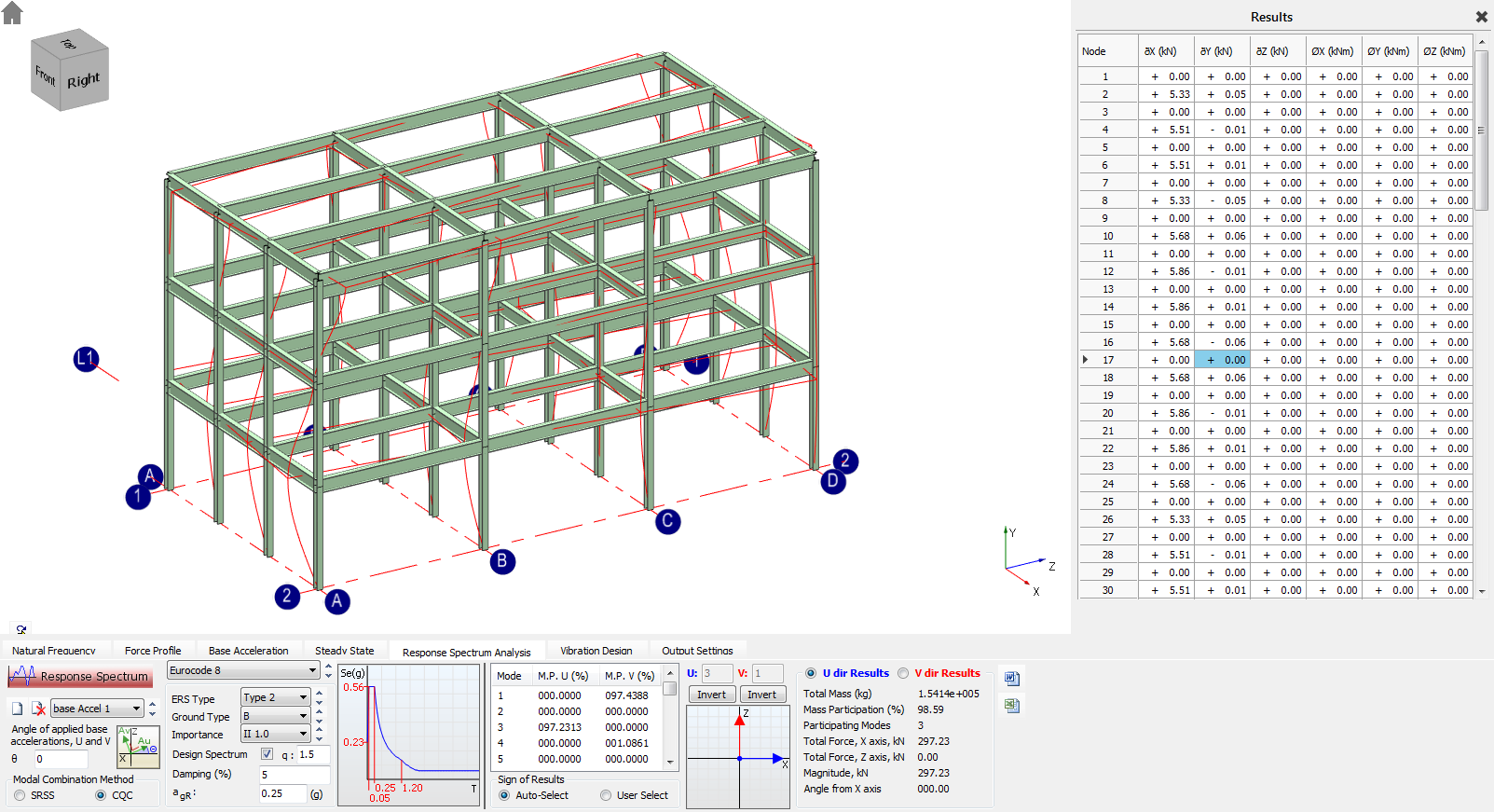
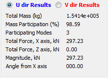
Once the response spectrum analysis is complete you can see the summary of the result in each direction on the right side of the tab. In addition, you can see the calculated nodal seismic forces for each of the nodes in the panel.
Attaching Seismic Forces to Static Load Cases
As a final step of the Modal Response Spectrum Analysis, we have to attach the calculated seismic forces to static load cases.
In the main File menu, select the Exist Dynamic Analysis option. Click Yes when prompted to save the changes.
Creating the Static Seismic Load Case
Before attaching the seismic forces we have to create a static seismic load case.
From the main Loads menu, select Load Cases option.
By default, there are already two (or three in case of using EC0 Eq. 6.10 a+b by default) combinations of actions and case titles generated.
- Load Case 001: Dead plus Live (Ultimate) (Permanent Plus Variable)
- Load Case 002: Live Only (Serviceability) (Variable Only)
We wish to create additional load cases for the seismic load combinations.
Using the 100% ‘+’ 30% combination rule of the Eurocode 8, there are eight different combinations of the horizontal seismic forces which need to be attached to the static loads.
To do this, we have to create eight additional load cases:
- Load Case 003: Dead plus Seismic (1.0V + 0.3U) (Ultimate)
- Load Case 004: Dead plus Seismic (1.0V - 0.3U) (Ultimate)
- Load Case 005: Dead plus Seismic (-1.0V + 0.3U) (Ultimate)
- Load Case 006: Dead plus Seismic (-1.0V - 0.3U) (Ultimate)
- Load Case 007: Dead plus Seismic (0.3V + 1.0U) (Ultimate)
- Load Case 008: Dead plus Seismic (-0.3V + 1.0U) (Ultimate)
- Load Case 009: Dead plus Seismic (0.3V - 1.0U) (Ultimate)
- Load Case 010: Dead plus Seismic (-0.3V - 1.0U) (Ultimate)
Click on the Add load
case ( ) button and type Dead
plus Seismic (1.0V + 0.3U) (Ultimate).
) button and type Dead
plus Seismic (1.0V + 0.3U) (Ultimate).
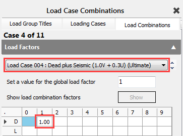
Move to the Load Combination tab and from the drop list select the recently created seismic load case.
Highlight the cell corresponding to D and 1 for group D1, then type a load factor of 1.0.
Move back to the Loading
Cases tab and while standing on the created seismic load cases
click on the Copy Case ( ) button to copy not just the title but the applied load
factor(s). Add another load case and using the Past Case (
) button to copy not just the title but the applied load
factor(s). Add another load case and using the Past Case ( ) button to past the title and the factor(s) from the
clipboard. Overwrite the title accordingly.
) button to past the title and the factor(s) from the
clipboard. Overwrite the title accordingly.
Repeat the previous process to create all of the eight seismic load cases.
Attaching Seismic Forces
From the main Loads menu, select Dynamic and Seismic Loads and then Seismic Loads option.
From the drop list, select the first seismic load case and Apply Seismic Loading by checking the checkbox.
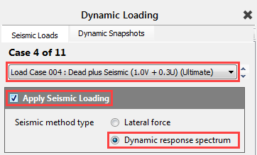
Select Dynamic response spectrum as Seismic method type.
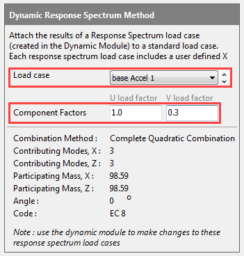
On the appeared Dynamic Response Spectrum Method dialogue, select the created base Accel 1 response spectrum load case and set the component factors according to the selected static load case (see the title of the selected load case above):
U load factor 1.0
V load factor 0.3
Repeat the same process for the rest of the seismic load cases.
Analysing the Frame
When the seismic forces are attached to the static load cases, the structure can be statically analysed and then designed.
From the main Analysis menu, select Static Analysis.
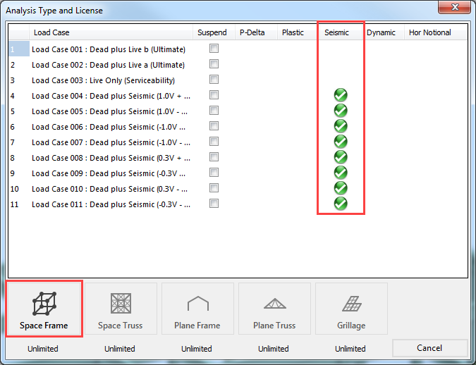
The green tick under the Seismic indicated that seismic forces are attached and will be statically analysed.
Click the Space Frame option to analyse as a continuous frame.
To view the results, from the main Results menu, select Graphic/Tabular Analysis Results option.
Lateral Force Method
The Lateral Force Method doesn’t require dynamic analysis.
The simplified seismic forces are defined using approximated expression defined in the design codes.
Defining the Seismic Forces and Attaching Them to Static Load Cases
As we previously created the necessary seismic load cases we can directly go to the definition of seismic forces.
From the main Loads menu, select Dynamic and Seismic Loads and then Seismic Loads option.
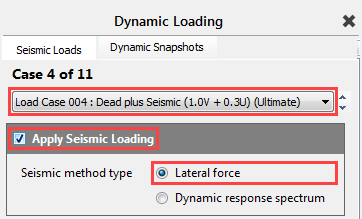
From the drop list, select the first seismic load case and change the Seismic method type to Lateral force.
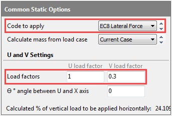
In the appeared Common Static Options field, set the Code to apply to EC8 Lateral Force method.
Leave on default Current Case the Calculate mass from the load case option.
Set the component factors (U and V) according to the selected static load case (see the title of the selected load case above):
U load factor 1.0
V load factor 0.3
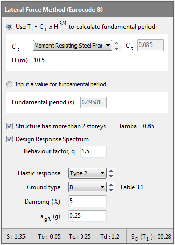
In the Lateral Force Method (Eurocode 8) field, select the first method to determine the fundamental period according to the provided approximated method of Eurocode.
For Ct select the Moment Resisting Steel Frame option, and leave on default value the H (m) which is the actual model height.
For the response spectrum, set the same parameter as before and shown by the image to the right.
Repeat the same process for the rest of the seismic load cases.
Analysing the Frame
When the seismic forces are set up and attached to the static load cases, the structure can be statically analysed and then designed as usual.
End
of Tutorial