T01-8 Wind loading
Wind load generation on a 3D structure acc. to Eurocode 1

Introduction
MasterFrame is a piece of advanced structural frame analysis software that allows you to analyse everything to beams, and trusses to multi-storey frames and complex 3D models in any type of material.
MasterKey:
Wind Analysis used with MasterFrame makes light work of the complex task of
applying wind loading to any structure; complete with automatic wind site
pressure calculation, full wind zoning and calculation of pressure coefficients
for absolutely any wind direction.
Overview & Outcome
In this tutorial, we will be using an existing small building model from the sample files with the aim of providing you with a solid understanding of:
Defining wind directions
Applying co-efficients of internal pressure and suction
Define wind panels on a 3D model
Choosing site location and building orientation
Viewing wind zoning and Cpe values
Open Existing File
On entering MasterFrame from the front screen the File Selector dialogue will now be displayed.
Using the file tree on the LHS, navigate to the C:\ProgramData\MasterSeries\SAMPLES folder on you computer.
From the list of models select 3D_Model_Wind_Loading.$5 file.
Click the Open button.

Design Code
We need to make sure we are using the Eurocode.
On the top menu, go to Design > Design Code and check the selected code which should be Eurocode. If not, please select it.
If you are asked “Do you wish to change the Loading Cases in accordance with the design code change” select Yes.
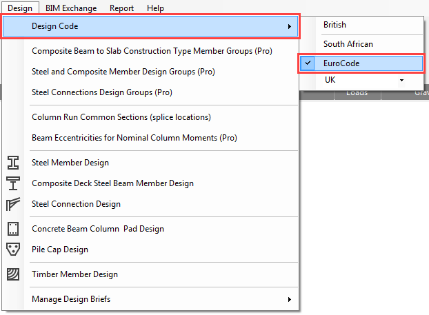
Go again to the Design > Design Code and check the national annex which should be the UK. If not, please select it.
If you are asked “Do you wish to change the Loading Cases in accordance with the design code change” select Yes.
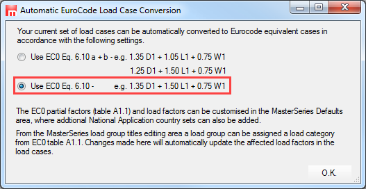
If you are asked which EC0 Eq. 6.10 set to use, choose the lower option 6.10.
Wind Directions and Settings
From the Loads and Wind Panel Loading (Pro) menu, select Wind Directions and Settings option.
Check the option Use MasterKey Wind Loading to generate the wind loading based on the site-specific parameters which will be defined later with MasterKey Wind Analysis module.
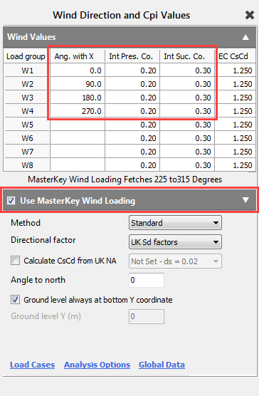
For calculation method we will use the default Standard method and the UK Sd factors for the directional factor.
Either enter the four wind directions as shown in the Ang. with X column, or double click twice the Ang. with X column heading to generate them automatically.
To add default internal and external pressure coefficients, double click on both Int Pres. Co. and Int Suc. Co. header as well. You can manually alter any of these values to allow for dominant openings.
Close the Wind Direction and Cpi Values dialogue by clicking on the X.
Wind Analysis
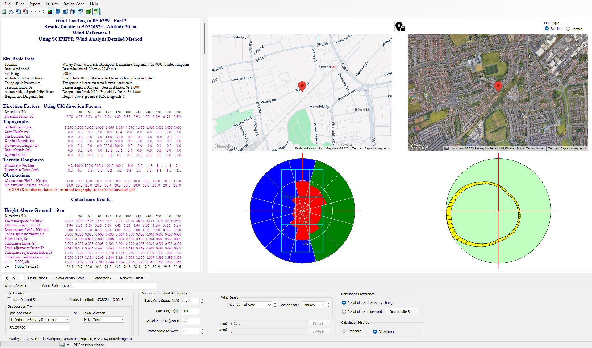
From the Loads and Wind Panel Loading (Pro) menu, select Site Data Wind Analysis option.
MasterKey Wind Analysis module will be opened in a new window.
Site location can be selected by using the maps to pick the location, or using one of the text search 'Type' inputs, or using the Town Selection list on the Site Data tab to pick one of the towns or cities from it.
Below the 'Ordnance Survey Reference' text search method is used, one entering the OS grid reference SD320379 and pressing the Enter key, the site is updated. Serach methods of Post Code, Easting Northing (UK), Easting Northing (IRL), Latitide Longitude and Eircode are available.
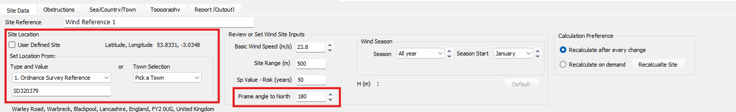
In the Frame angle to the North box, type 180 degrees to specify the anti-clockwise angle between the frame Z axis and magnetic north.
As the site is selected and updated, the main data of Basic Wind Speed, Site Altitude, 'Obstructions', 'Sear/Town/Country' (terrain roughness) and 'Topography' are automatically determined. The new wind site pressure caulations are updated and presented in the deisgn output windows
Further custom changes can be made to the site data, the program automatically calculates all required q values for the frame at the various building levels. Obstructions and topography data is automatically determined for the chosen site location, and can be examined in their separate tabs.
From the file menu, select File and Exit MasterKey Wind.
Defining The Wind Loading Panels
From the Loads menu, select Wind Panel Loading (Pro) and then Wind Panels – Wall and Roof.
Now we will demonstrate the procedure for setting up the wind loaded surfaces manually.
South face of the building
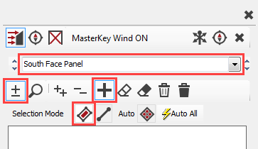
To define a new group (if it is
not created by default), select the Add new
group (
 ) button and type South
Face Panel.
) button and type South
Face Panel.
Ensure that you are in Add/remove
items ( ) mode and change the Selection Mode
to Select Panels (
) mode and change the Selection Mode
to Select Panels (
 ).
).
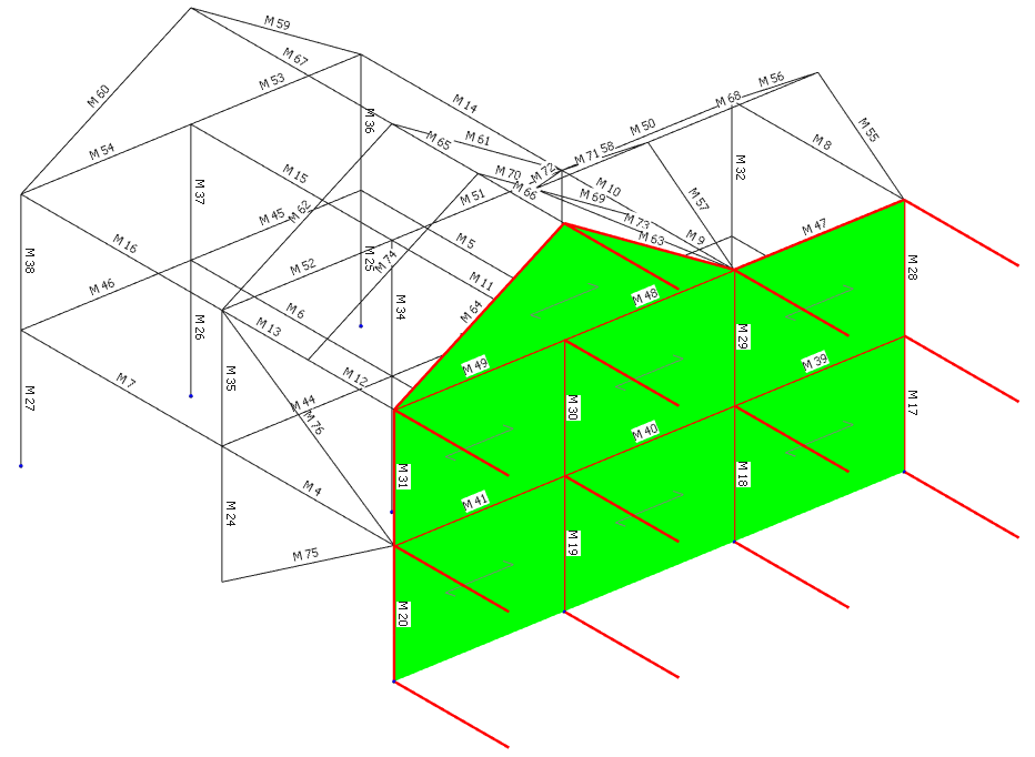
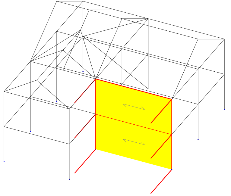
Select all the panels on the surface.
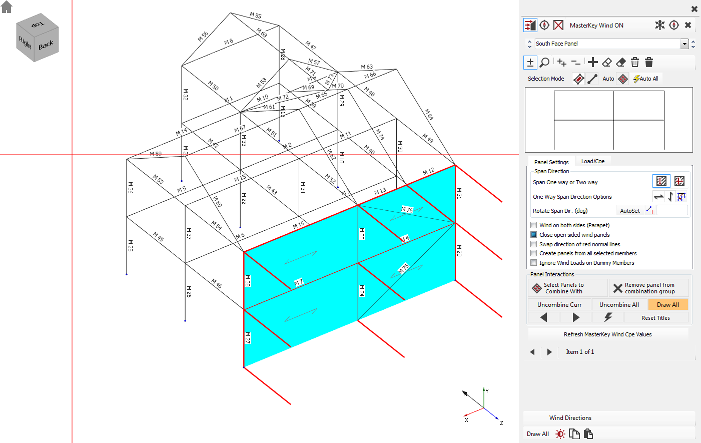
Note that bracing members (M75 and M76) have not been highlighted as they have been defined as bracing members.
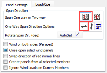
If the panels are set to span
vertically, change it to the Span
horizontally ( ) option.
East Face Panel
Click on the Add new group (
) button and type South
Face Panel.
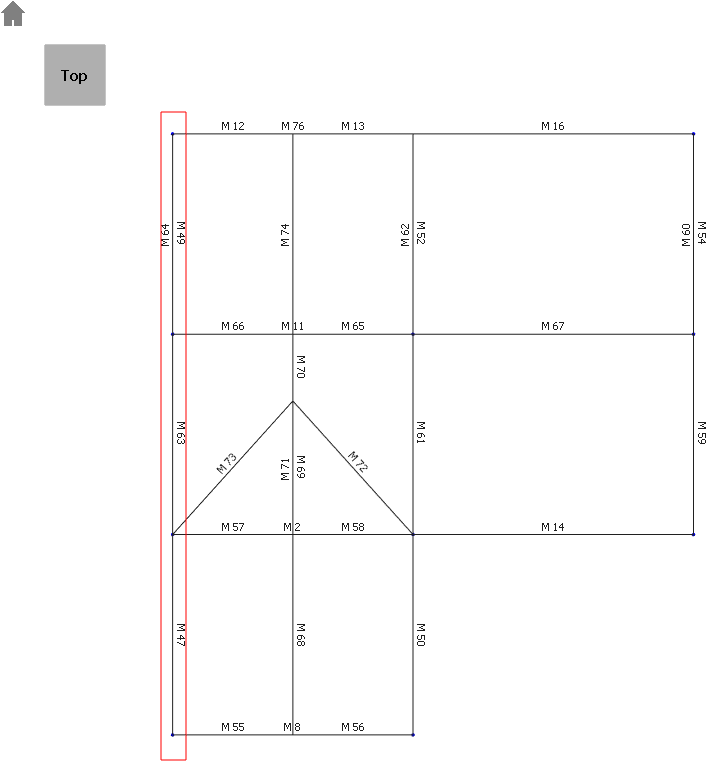
Place the model in plan view by
selecting the Top side of the
viewing cube ( ).
).
Window all members along the west elevation.
Place the structure back in isometric
view by clicking on the Home
(
 ) button.
Using the Fast select of wind panel function
This method is used to quickly select a panel of any orientation. You can simply pick a point within a panel to automatically select all panels within the range and plane. This avoids having to individually select the panels, or cross windowing groups of panels where window selection is difficult.
To fast selection mode, select
the Fast select of wind panel
( ) button.
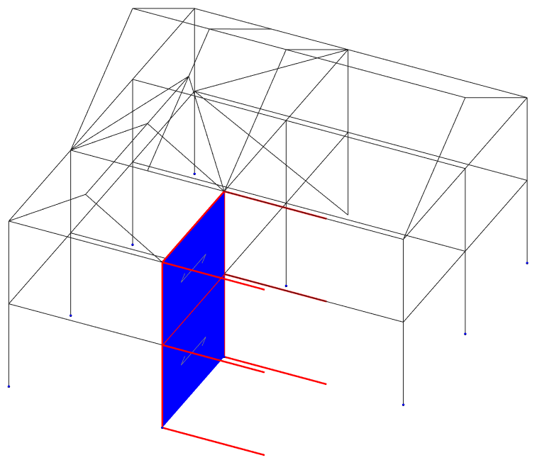
Click on the Add new group (
) button to define a new wind panel and name it to North Face Panel 1.
Ensure that you are in Add/remove
items (
) mode.
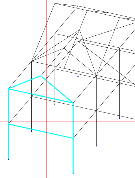
Click any point within the front panel to select the whole front panel.
This method is most useful for creating panels that are in non-orthogonal orientations and contain a large number of members.
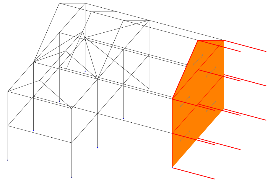
Remaining in Fast select of wind panel (
), create the wind panels as shown below with their
corresponding names.
|
|
|
|
|
North Face Panel 2 |
West Face Panel 1 |
West Face Panel 2 |
This completes the wind panel definitions for the walls. At this stage you should have only six wind panels. Next, we’ll create the remaining four panels in the roof.
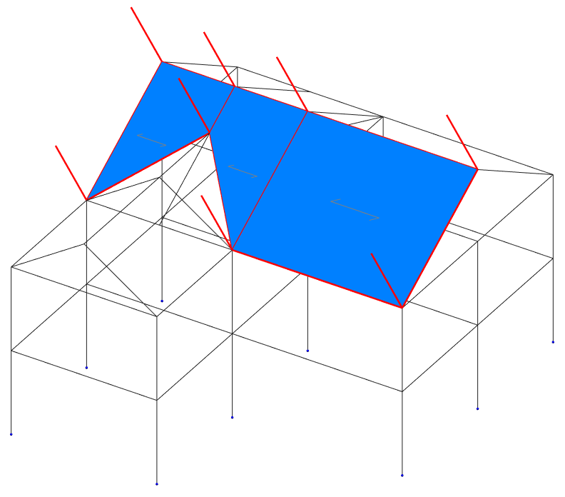
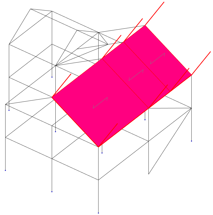
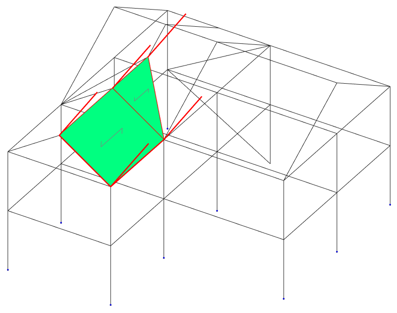
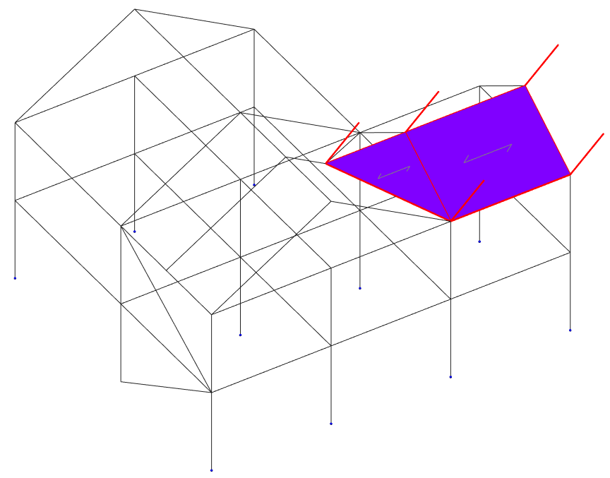
Remaining in Fast select of wind panel (
), create the wind panels as shown below by selecting a member
in each panel and naming them.
|
|
|
|
North Roof Panel |
South Roof Panel |
|
|
|
|
West Roof Panel |
East Roof Panel |
Select Draw All from the very bottom left-hand-side of the panel to see all of the created panels.
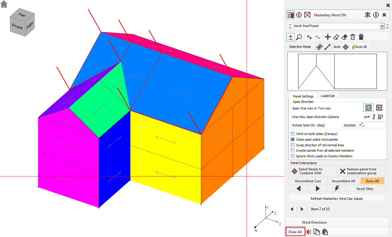
All your wind panels have now been defined. Each panel definition will be shown in a different colour.
Close the Wind Panel Generation dialogue by clicking the X button on the top right-hand-side.
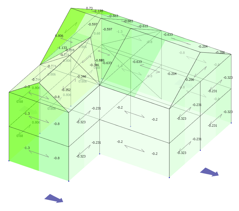
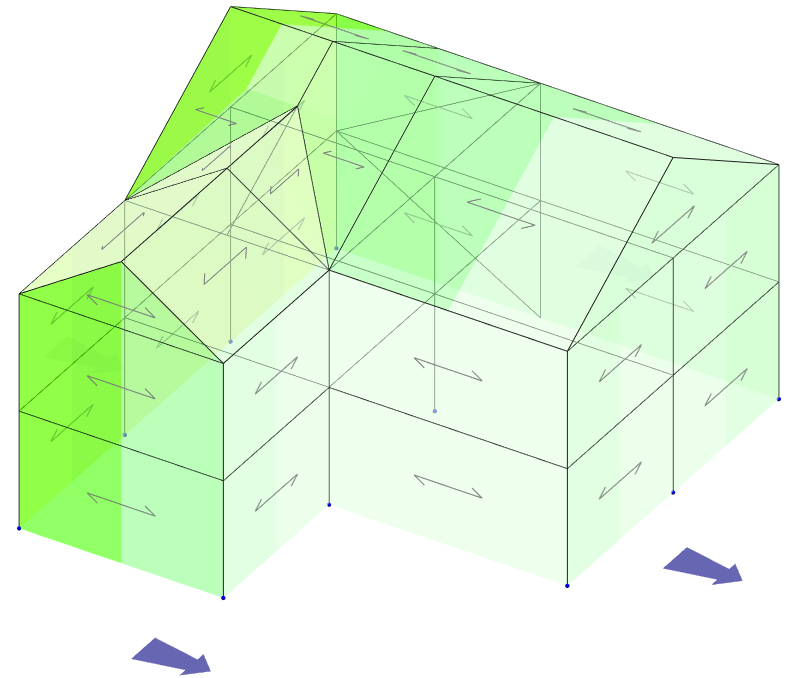
Viewing the Wind Loads
Turn on the Wind ( ) button in the Wind Load
group to display all the wind panels.
) button in the Wind Load
group to display all the wind panels.
Select W1 direction
from the Direction (
 ) drop-down list. When we set up wind loading, we choose 4
wind directions, 0, 90, 180 & 270
degrees to the X-Axis. W1 refers to
the first direction, 0 deg.
) drop-down list. When we set up wind loading, we choose 4
wind directions, 0, 90, 180 & 270
degrees to the X-Axis. W1 refers to
the first direction, 0 deg.
Green is suction/uplift, and yellow is pressure. The darker colour indicates a higher intensity.
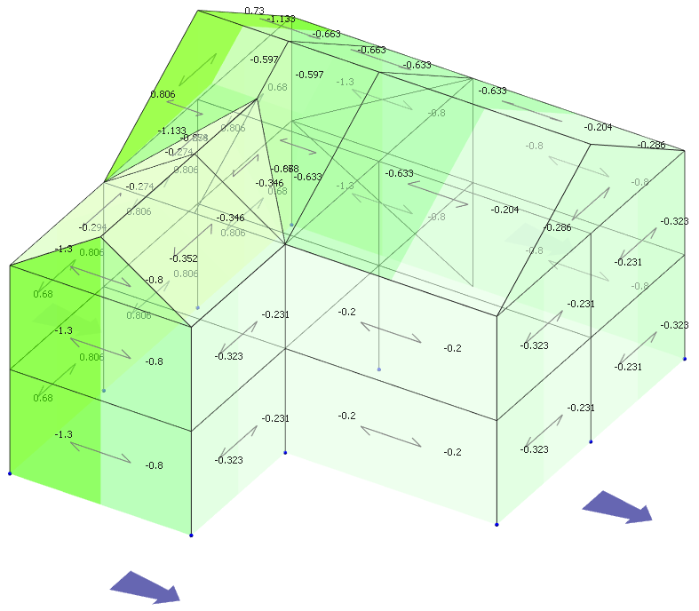
Turn on Coef Values ( ) to see the coefficients on each surface.
Now turn on the Pressure ( ) values. These are the values with no internal suction or
pressure.
) values. These are the values with no internal suction or
pressure.
- Scroll through directions W1 to W4. W5-W8 is blank as we only set up four wind directions.
- Select direction P1. The values change as P1, is W1, with internal Pressure added.
- Select direction S1. The values change as S1, is W1, with internal Suction added.
Direction Max / Min shows the maximum pressures (down/inward) and suctions (up/outward) on each of the panels. Max & Min are very useful for cladding design.
Finally, return to W1 and select Wind Zone ( ). This gives you all the zones used in calculating the wind coefficients.
Load Cases
We now have to apply all the calculated wind loads into loading cases.
Select Loads and then Load Cases from the file menu.
By default, there are already two (or three in case of using EC0 Eq. 6.10 a+b by default) combinations of actions and case titles generated.
Load Case 001: Dead plus Live (Ultimate) (Permanent Plus Variable)
Load Case 002: Live Only (Serviceability) (Variable Only)
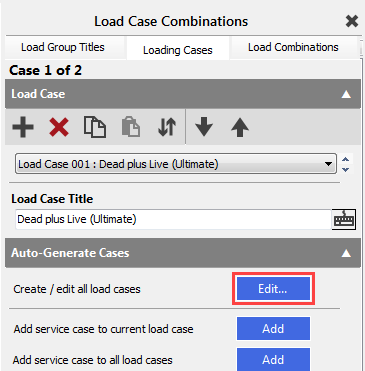
We will auto-generate and add the all of the wind load cases to the existing onces.
In the Auto-Generate Cases field, select Create/edit all load cases by pressing the Edit… button.
In this tab, we have the facilities to manage loading cases and define titles for them. However, for this example, we will retain the default loading cases and titles.
Uncheck Dead+Live, Live Only and Dead Only templates because we will not generate them now.
Select only the Dead+Live+Wind template and edit as follows.
D0, D1, L1, W-All are all selected. W-All contains all of the different wind direction load cases.
TIP! If W-All is hidden, then untick List used load groups only to display it.
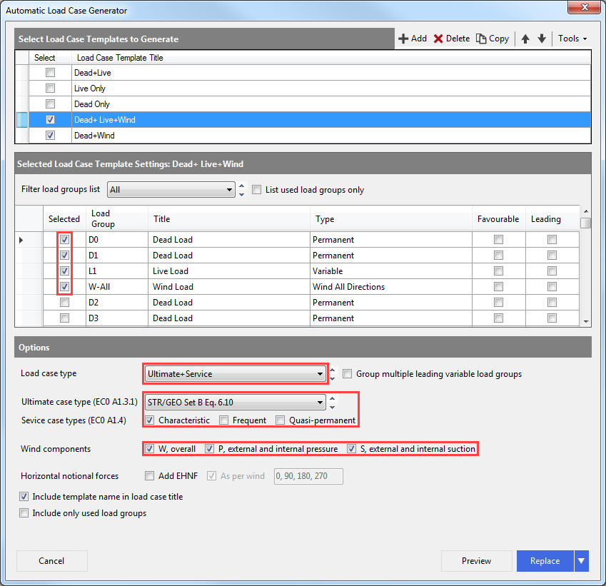
Select the Dead + Wind template and edit as previously.
D0, D1, W-All are all selected. L1 is neglected at this time.
Select the Preview button, and you will see all the loading cases.
Close the Preview window and click on the arrow button near the Replace button and select the Add to existing cases option.
Click on the Add button. You now have 66 loading cases.
End of Tutorial
